
Foundation pit anchor cable cutting machine

A cable cutting machine and foundation pit technology, which is applied in the direction of infrastructure engineering, construction, sheet pile walls, etc., can solve the problems of low cutting efficiency, high labor intensity, and poor cutting accuracy, and achieve the effect of precise cutting and positioning

Pending Publication Date: 2021-04-16
长沙垚森工程科技有限公司
View PDF0 Cites 0 Cited by
  • Summary
  • Abstract
  • Description
  • Claims
  • Application Information

AI Technical Summary

Problems solved by technology

[0003] The traditional cutting method mainly relies on manually positioning the anchor cables to be cut, and then the construction personnel use the cutting equipment to cut according to the needs, which has the disadvantages of low cutting efficiency, poor cutting accuracy, and high labor intensity

Method used


Image

  • Foundation pit anchor cable cutting machine
  • Foundation pit anchor cable cutting machine
  • Foundation pit anchor cable cutting machine

Examples


Embodiment Construction

[0020] The present invention will be further described below according to the accompanying drawings.

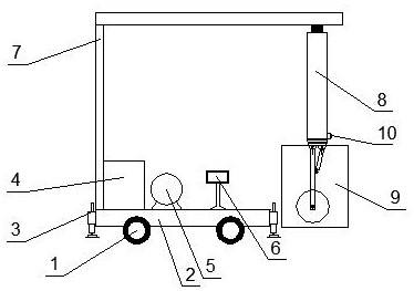
[0021] Such as figure 1 As shown, the foundation pit anchor cable cutting machine includes: traveling device 1, chassis 2, balance support device 3, hydraulic oil tank 4, hydraulic oil pump 5, electronic display screen 6, l-shaped cantilever steel member 7, telescopic device 8, fixed Cutting device 9, miniature electronic camera 10. walking device 1 is arranged on the bottom of chassis 2, balance supporting device 3 is set around chassis 2, hydraulic oil tank 4, hydraulic oil pump 5, and electronic display screen 6 is all placed on the top of chassis 2; l Type cantilever steel member is fixed on the left side edge of chassis 2, telescopic device 8 is arranged on the l-shaped cantilever steel member 7, microelectronic camera 10 is housed below telescopic device 8, and fixed cutting device 9 is hinged below the telescopic device.

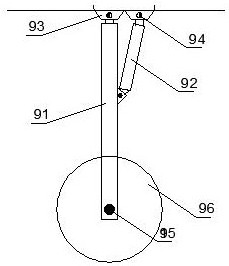
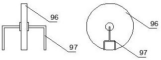
[0022] Such as figure 2 As shown, the fixed...


PUM


Abstract

The invention belongs to the technical field of foundation pit anchor cable construction, and particularly relates to a foundation pit anchor cable cutting machine used during foundation pit secondary treatment. The foundation pit anchor cable cutting machine comprises a traveling device, a chassis, balance supporting devices, a hydraulic oil tank, a hydraulic oil pump, a telescopic device, a fixed cutting device, a micro camera and an electronic display screen, wherein the fixed cutting device is arranged at one end of the telescopic device, the micro camera is fixed below the telescopic device, the telescopic device is connected with the chassis through an l-shaped cantilever steel component, the l-shaped cantilever steel component is fixed to the left side of the chassis, the balance supporting devices are arranged on the periphery of the chassis, the traveling devices, the hydraulic oil tank and the hydraulic oil pump are arranged at the bottom of the chassis, and the electronic display screen is arranged above the chassis. According to the foundation pit anchor cable cutting machine, a special telescopic and cutting device can directly enter a narrow working face with a limited space for anchor cable cutting, large-range working platform construction is avoided, the working efficiency is improved especially in the secondary treatment environment of an existing foundation pit, and excessive disturbance of the soil body condition of the foundation pit is avoided.

Description

technical field [0001] The invention belongs to the technical field of foundation pit anchor cable construction, and in particular relates to a foundation pit anchor cable cutting machine for secondary treatment of foundation pits. Background technique [0002] With the continuous advancement of China's modernization process, various high-rise and super high-rise building structures have sprung up, causing a huge number of foundation pit support anchor cables to be buried underground, and the foundation pit anchor cables that are no longer used will be built around The foundation pit has adverse effects. [0003] The traditional cutting method mainly relies on manually positioning the anchor cables to be cut, and then the construction personnel use cutting equipment to cut according to needs, which has the disadvantages of low cutting efficiency, poor cutting accuracy, and high labor intensity. Therefore need a kind of simple, time-saving and labor-saving and do not need ...

Claims


Application Information

Patent Timeline
Patent Type & Authority Applications(China)
IPC IPC(8): E02D9/00E02D5/76
Inventor 陈宝光王振宇任加琳赵晓薇汪优
Owner 长沙垚森工程科技有限公司
Learn More