
Self-centering mechanism for large-diameter centering rotary equipment

A self-centering, large-diameter technology, applied to the rigid support of mechanical equipment, bearing components, shafts and bearings, etc., can solve the problems of difficult to ensure accuracy, easy pitting of raceways, unstable transmission, etc., to ensure The effect of assembly accuracy, effective positioning support, and convenient adjustment and positioning

Active Publication Date: 2021-04-16
TIDFORE HEAVY IND
View PDF8 Cites 1 Cited by
  • Summary
  • Abstract
  • Description
  • Claims
  • Application Information

AI Technical Summary

Problems solved by technology

However, with this structure, it is difficult to accurately center the rolling pair, and the adjustment of the gap between the support wheel and the raceway is labor-intensive and time-consuming, and it is difficult to ensure the gear meshing backlash when the sun gear and the planetary gear transmission pair are installed on the center column. Requirements for the accuracy required when mounting the swivel arm on the frame
As a result, during the operation of the equipment, there are often phenomena such as uneven force on the support wheels, easy pitting on the raceway, unstable transmission, vibration, and loud noise, which increases the workload of equipment installation, adjustment, and daily maintenance.

Method used


Image

  • Self-centering mechanism for large-diameter centering rotary equipment
  • Self-centering mechanism for large-diameter centering rotary equipment
  • Self-centering mechanism for large-diameter centering rotary equipment

Examples


Embodiment 1

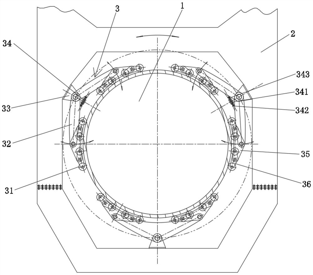
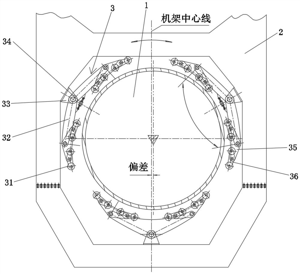
[0029] figure 1 and figure 2 It shows the first embodiment of the self-centering mechanism of the present invention for large-diameter centering and rotating equipment. In this embodiment, it is the structural form of internal centering and external rotation. In order to facilitate the description of the structure and working principle of the present invention, set The fixed part is the central column 1, and the rotating part is the frame 2. The frame 2 rotates around the center column 1 through a self-centering mechanism, the center column 1 is fixed, the frame 2 is positioned on the raceway circle of the center column 1, and rotates around its central axis.

[0030] The self-centering mechanism is arranged between the center column 1 and the frame 2. The self-centering mechanism includes at least two groups of rolling units 3, at least two groups of rolling units 3 are located at different positions in the circumferential direction of the outer circumferential surface of t...

Embodiment 2

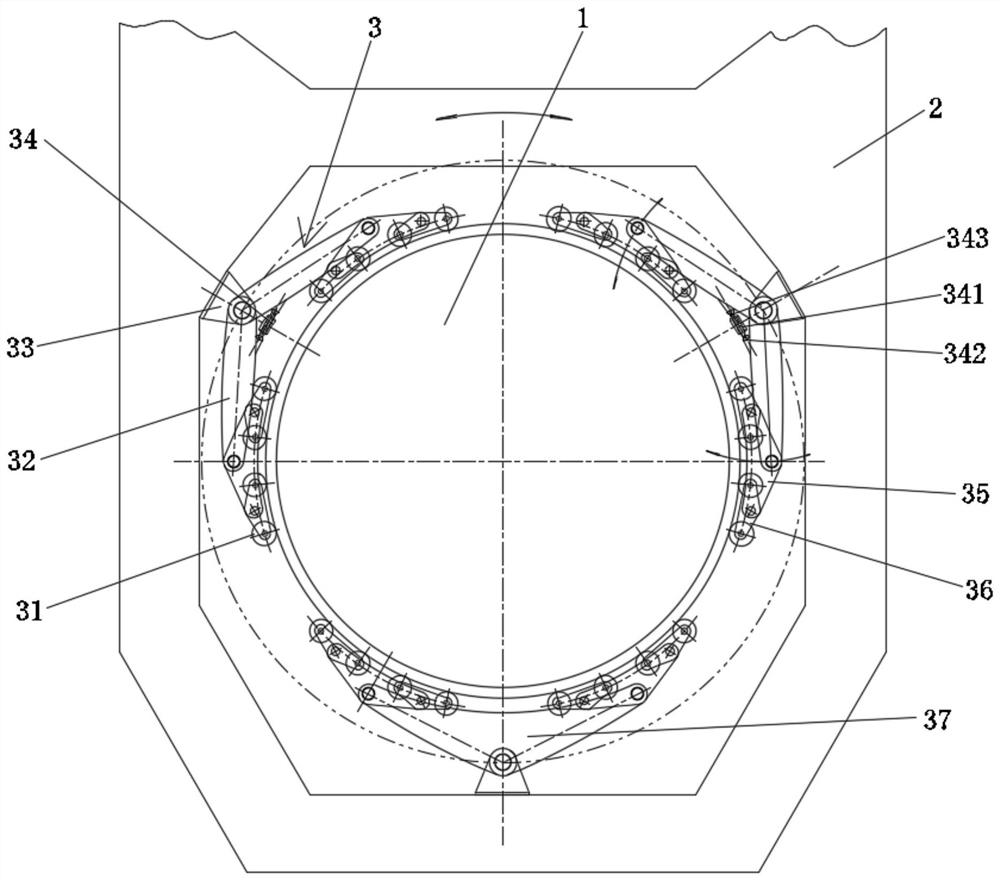
[0045] image 3 and Figure 4 It shows the second embodiment of the self-centering mechanism of the present invention for large-diameter centering and rotating equipment. In this embodiment, it is the structural form of external centering and internal rotation. In order to facilitate the description of the structure and working principle of the present invention, Let the fixed part be the central column 1 frame 2, and the rotating part be the central column 1. The frame 2 is provided with an inner chamber, and the central column 1 rotates in the inner cavity of the frame 2 through a self-centering mechanism. The frame 2 is fixed, and the central column 1 is provided with a raceway circle, and rotates around its central axis.

[0046] The self-centering mechanism is arranged between the center column 1 and the frame 2. The self-centering mechanism includes at least two groups of rolling units 3, at least two groups of rolling units 3 are located at different positions in the c...


PUM


Abstract

The invention discloses a self-centering mechanism for large-diameter centering rotary equipment. The rotary equipment comprises a fixed part and a rotating part, wherein the self-centering mechanism is arranged between the fixed part and the rotating part; one of the fixed part and the rotating part is cylindrical while the other one is provided with a corresponding inner cavity; the cylinder is located in the inner cavity; a roller path is arranged on the outer circumferential surface of the cylinder; the self-centering mechanism comprises at least two groups of rolling units, wherein at least one group of rolling units are adjusting units used for adjusting the position of the rotating part; at most one group of rolling units are positioning units, and the positioning units are arranged at the positioning reference of the fixed part; and the rotating part concentrically rotates relative to the fixed part through the adjusting units. According to the self-centering mechanism for the large-diameter centering rotary equipment, an aligning tool does not need to be additionally arranged, automatic centering is achieved, the assembly precision of a rolling pair is high, stress is balanced, and the self-centering mechanism is suitable for an inner centering outer rotation mechanism or an outer centering inner rotation mechanism.

Description

technical field [0001] The invention relates to the structural technical field of large-scale construction machinery rotating equipment, in particular to a self-centering mechanism for large-diameter centering and rotating equipment. Background technique [0002] In construction machinery, based on comprehensive factors such as cost, environmental conditions, and ease of implementation, a guide wheel raceway structure is used as a rotary centering and radial support mechanism for large-diameter inner rotary parts. In this structure, the center of the inner cavity of the frame is the center of rotation of the central column. There are several support wheels installed on the frame, usually 4, 6, 8... etc. even numbers according to the diameter of the center column, generally distributed evenly and symmetrically with the center column, these support wheels are constrained by the raceway pre-positioned on the center column , so as to realize the positioning of the center of the...

Claims


Application Information

Patent Timeline
Patent Type & Authority Applications(China)
IPC IPC(8): F16C35/04
Inventor 孟庆耀肖红波
Owner TIDFORE HEAVY IND
Learn More