A waste heat recovery and utilization device of coal gangue brick roasting equipment
A waste heat recovery and coal gangue technology, applied in lighting and heating equipment, preheating fees, charging support, etc., can solve problems such as waste of resources and ineffective use of heat, and achieve the effect of improving quality
- Summary
- Abstract
- Description
- Claims
- Application Information
AI Technical Summary
Problems solved by technology
Method used
Image
Examples
Embodiment 1
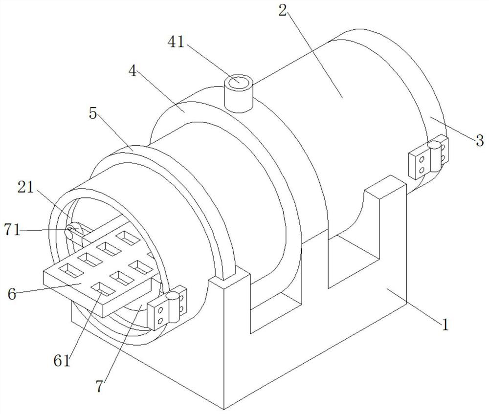
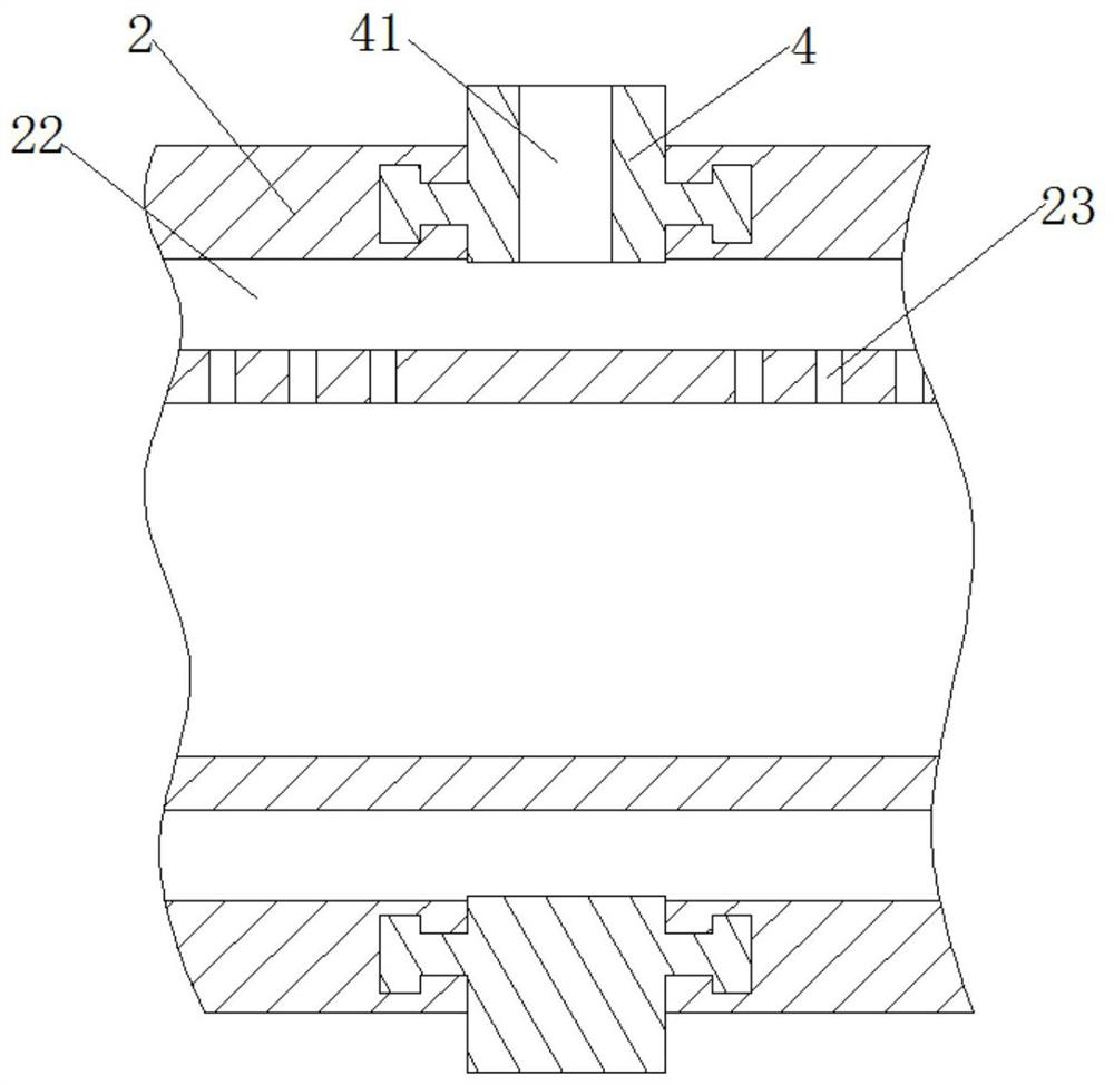
[0023] see Figure 1-4 , this embodiment provides a waste heat recovery and utilization device for coal gangue brick roasting equipment, including a bearing bracket 1, the upper end of the bearing bracket 1 is provided with a rotatable drum 2 for transferring heat, and the coal gangue brick is roasted through the drum 2. The waste heat is transferred to the inner cavity of the drum 2, and the inner cavity of the drum 2 is heated;
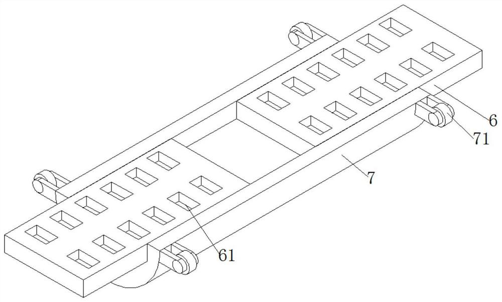
[0024] The inner cavity of the drum 2 is provided with a bearing plate 6 for carrying the bricks and keeping the bricks upward in real time. The bearing plate 6 keeps the bricks upward in real time to prevent the bricks from falling from the bearing plate 6 when the drum 2 moves.
[0025] In order to facilitate the placement of the bricks, the upper end surface of the carrier plate 6 is evenly provided with rectangular grooves 61 for placing bricks. Placing the rectangular bricks in the rectangular grooves 61 can prevent the bricks from being deform...
Embodiment 2
[0036] see Figure 5 , made further improvements on the basis of Example 1:
[0037] In order to prevent the counterweight 7 and the bearing plate 6 from rotating relative to the drum 2 when the brick is placed, the lower end surface of the bearing plate 6 is provided with a fixing mechanism 8 for fixing the counterweight 7 relative to the drum 2. The counterweight 7 and the carrier plate 6 rotate relative to the drum 2 .
[0038] The fixing mechanism 8 includes an oblique groove 82, a movable rod 81 and a limit groove 86. The inclined groove 82 is located on the lower end surface of the carrier plate 6, and the limit groove 86 is located on the inner cavity wall of the drum 2. The movable rod 81 Passing through the counterweight 7, one end of the movable rod 81 is slidingly attached to the oblique side of the chute 82, and the end of the movable rod 81 away from the chute 82 is inserted into the limit slot 86, and the movable rod 81 is connected to the limit The slot 86 is ...
PUM
 Abstract
Description
Claims
Application Information
 - R&D
- Intellectual Property
- Life Sciences
- Materials
- Tech Scout
- Unparalleled Data Quality
- Higher Quality Content
- 60% Fewer Hallucinations
Browse by: Latest US Patents, China's latest patents, Technical Efficacy Thesaurus, Application Domain, Technology Topic, Popular Technical Reports.
© 2025 PatSnap. All rights reserved.Legal|Privacy policy|Modern Slavery Act Transparency Statement|Sitemap|About US| Contact US: help@patsnap.com


