A structure and construction method for detecting surface curvature of supporting crown beams

A surface bending and crown beam technology is applied in the structure and construction field to detect the surface curvature of support crown beams, which can solve the problems of waste of resources, low mechanical automation, and heavy user workload, and achieve fast and stable support and automatic construction. High, time-saving and labor-saving pouring effect

Active Publication Date: 2022-05-27
京兴国际工程管理有限公司
View PDF4 Cites 0 Cited by
  • Summary
  • Abstract
  • Description
  • Claims
  • Application Information

AI Technical Summary

Problems solved by technology

[0007] In order to solve the existing protective support structure construction for rapid pouring crown beams, during construction, the supports are mostly assembled on site at zero time, and there is a welding assembly method, resulting in supports that can only be used for the current construction site. However, it cannot be recycled for secondary use, resulting in reduced construction efficiency and waste of resources. Most of the construction steps are completed manually. In the process of vibrating concrete, the mechanical automation is relatively low. Since the vibration requires quick insertion and slow extraction, and It is also necessary to avoid the contact between the surface of the vibrating pump head and the formwork, the bottom of the mold and the steel bar layer, which will cause the user to spend a lot of time and energy to frequently move the position of the vibrating equipment itself and the use position, and the technical problem that the user has a large workload , the present invention provides a structure and construction method for detecting the curvature of the surface of the supporting crown beam, for solving the above problems

Method used


Image

  • A structure and construction method for detecting surface curvature of supporting crown beams
  • A structure and construction method for detecting surface curvature of supporting crown beams
  • A structure and construction method for detecting surface curvature of supporting crown beams

Examples


Embodiment 1

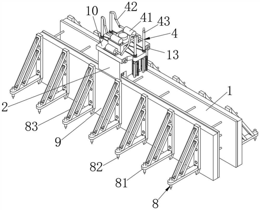
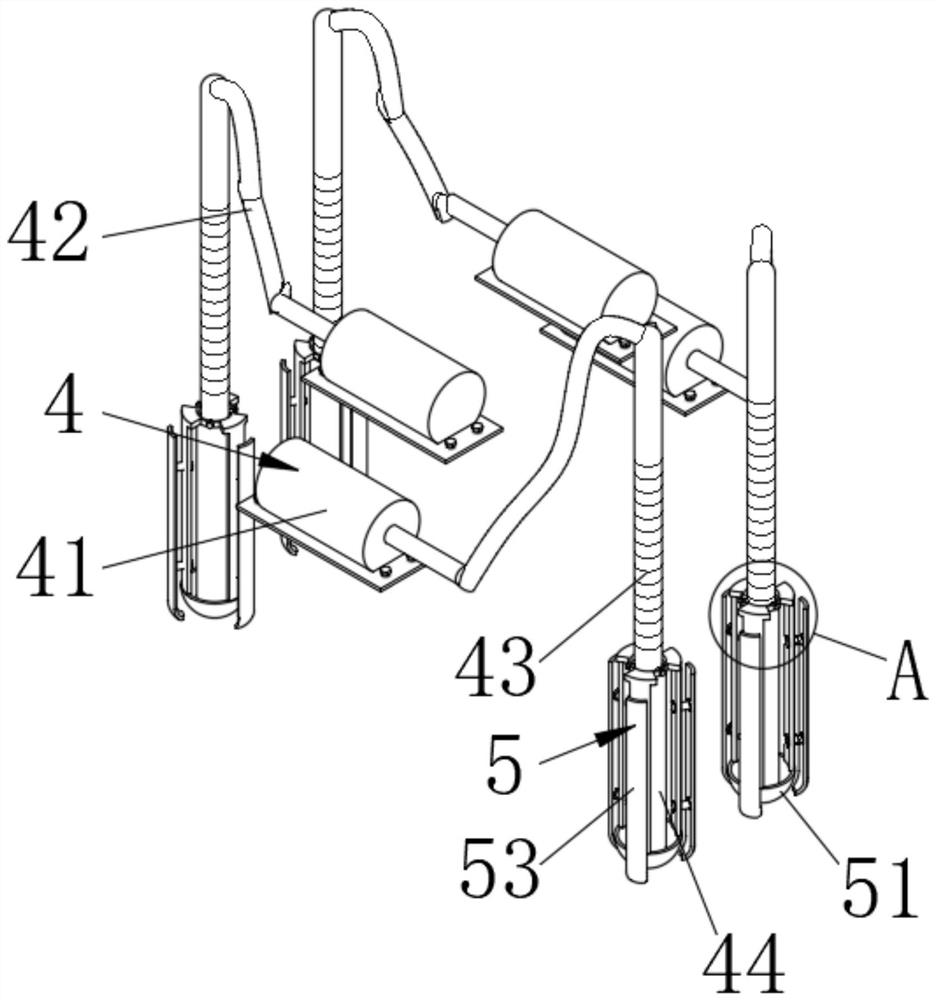
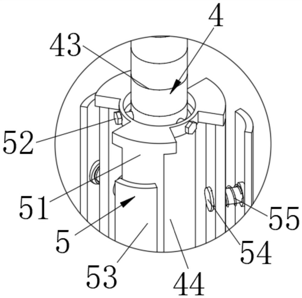
[0046] combine Figure 1-9 , the embodiment of the present invention discloses a structure for detecting the curvature of the surface of the support crown beam, including a template body 1, the number of the template body 1 is two, the top of the template body 1 is provided with a frame 2, and the The bottom is provided with a drive mechanism 1 3, the drive mechanism 1 3 includes a motor 1 31 installed at the bottom of the frame 2, the output shaft of the motor 1 31 is fixedly connected with a drive bevel gear 32, and both sides of the bottom of the frame 2 are provided with rectangular cavities The body 33, the front side and the rear side of the inner cavity of the rectangular cavity 33 are provided with runners 34, a transmission rod 36 is fixedly connected between the two runners 34 on the front side, and the surface of the transmission rod 36 is fixedly connected with a stress cone The gear 35, the force bevel gear 35 and the drive bevel gear 32 mesh with each other, and ...

Embodiment 2

[0051] combine Figure 1-9 , the embodiment of the present invention discloses a structure for detecting the curvature of the surface of the support crown beam, including a template body 1, the number of the template body 1 is two, the top of the template body 1 is provided with a frame 2, and the The bottom is provided with a drive mechanism 1 3, the drive mechanism 1 3 includes a motor 1 31 installed at the bottom of the frame 2, the output shaft of the motor 1 31 is fixedly connected with a drive bevel gear 32, and both sides of the bottom of the frame 2 are provided with rectangular cavities The body 33, the front side and the rear side of the inner cavity of the rectangular cavity 33 are provided with runners 34, a transmission rod 36 is fixedly connected between the two runners 34 on the front side, and the surface of the transmission rod 36 is fixedly connected with a stress cone The gear 35, the force bevel gear 35 and the drive bevel gear 32 mesh with each other, and ...


PUM


Abstract

The invention relates to a structure and a construction method for detecting the surface curvature of a supporting crown beam, and relates to the technical field of crown beam construction. The present invention comprises template body, and the quantity of template body is two, and the top of template body is provided with frame, and the bottom of frame is provided with drive mechanism 1, and drive mechanism 1 includes motor 1 installed at the bottom of frame, the output of motor 1 The shaft is fixedly connected with a driving bevel gear. In the present invention, the formwork body and the beam plate are limited and supported through the cooperative use of the tensioning mechanism and the support mechanism, so that the formwork body is closely attached to the surface of the steel bar layer, and then through the setting of the driving mechanism one, the drive frame is placed on the formwork body In the process of walking on the top of the machine frame, through the cooperation of the driving mechanism 2 and the vibrating mechanism, the concrete is vibrated vertically, so as to achieve the purpose of fast and stable support, time-saving and labor-saving pouring, and high construction automation. .

Description

technical field [0001] The invention relates to the field of building construction detection, in particular to a structure and a construction method for detecting the surface curvature of a support crown beam. Background technique [0002] The crown beam is the reinforced concrete continuous beam set on the top of the supporting (enclosure) structure (mostly piles and walls) around the foundation pit. One of its functions is to connect all the pile foundations together (such as bored piles). , rotary excavation of cast-in-place piles, etc.) to prevent the top edge of the foundation pit (shaft) from collapsing. The second is to bear the horizontal pressing force and vertical shear force of the steel support (or reinforced concrete support) through the corbel. The crown beam construction must be Chisel off the laitance on the top of the pile, etc. [0003] During the construction of the crown beam, affected by the shape of the construction position, it is necessary to carry o...

Claims


Application Information

Patent Timeline
Patent Type & Authority Patents(China)
IPC IPC(8): G01B11/24E02D17/04E02D15/02
Inventor 谢岩闫慧李晓龙
Owner 京兴国际工程管理有限公司
Why Eureka
Try Eureka