Control circuit of medical equipment disinfection device for anesthesia department

A technology for controlling circuits and medical equipment, applied in the medical field, can solve problems such as heavy workload and cumbersome operation process

Pending Publication Date: 2021-04-16
马宏
View PDF0 Cites 8 Cited by
  • Summary
  • Abstract
  • Description
  • Claims
  • Application Information

AI Technical Summary

Problems solved by technology

[0004] In order to overcome the shortcomings of people manually cleaning and disinfecting medical equipment, the whole process requires people to manually operate, people's work load is very heavy, and the operation process is cumbersome. The technical problem to be solved is: to provide a method that can reduce people's work burden , easy-to-operate anesthesia department medical equipment disinfection device control circuit

Method used


Image

  • Control circuit of medical equipment disinfection device for anesthesia department
  • Control circuit of medical equipment disinfection device for anesthesia department

Examples


Embodiment approach 1

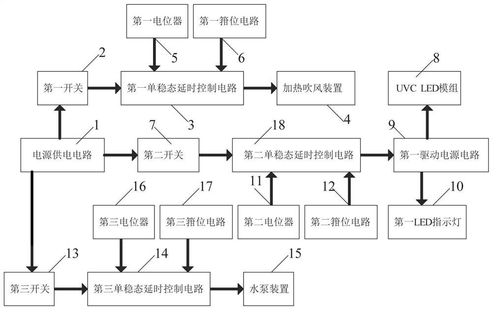
[0022] A control circuit of a medical equipment disinfection device used in an anesthesia department, such as figure 1As shown, it includes a power supply circuit 1, a second switch 7, a UVC LED module 8, a first driving power circuit 9, a first LED indicator light 10, a second potentiometer 11, a second clamping circuit 12, a third Switch 13, the third monostable delay control circuit 14, water pump device 15, the third potentiometer 16, the third clamping circuit 17 and the second monostable delay control circuit 18, the second switch 7 and the first The input end of two monostable delay control circuits 18 is connected, and the output end of the second monostable delay control circuit 18 is connected with the input end of the first drive power supply circuit 9, and the UVC LED module 8 and the first drive power supply circuit 9 are connected. An LED indicator light 10 is all connected with the output end of the first driving power supply circuit 9, and the second potentiome...

Embodiment approach 2

[0025] On the basis of Embodiment 1, such as figure 1 As shown, it also includes a first switch 2, a first monostable delay control circuit 3, a heating and blowing device 4, a first potentiometer 5 and a first clamping circuit 6, the first switch 2 and the first monostable The input end of the steady-state delay control circuit 3 is connected, the output end of the first monostable delay control circuit 3 is connected with the heating and blowing device 4, and the first potentiometer 5 and the first clamping circuit 6 are all connected with The input terminal of the first monostable delay control circuit 3 is connected, and the power supply circuit 1 is the first switch 2, the first monostable delay control circuit 3, the heating and blowing device 4, the first potentiometer 5 and the first potentiometer 5. A clamping circuit 6 supplies power.

[0026] People can set the delay time of the heating and blowing device 4 by the first potentiometer 5, and then the first switch 2,...

Embodiment approach 3

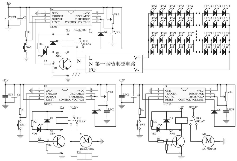
[0028] A control circuit of a medical equipment disinfection device used in an anesthesia department, such as figure 2 As shown, the second monostable delay control circuit 18 includes a time-base integrated circuit NE555-U2, a tact switch SW2, a capacitor C2, an electrolytic capacitor EC3-electrolytic capacitor EC4, a resistor R5-resistor R8, a diode D3-diode D4, relay RL2, transistor Q2 and light-emitting diode VD2, the 6-pin of the time-base integrated circuit NE555-U2 is connected to its 7-pin, the 1-pin of the time-base integrated circuit NE555-U2 is grounded, and the time-base integrated circuit NE555 - Both pin 4 and pin 8 of U2 are connected to +12V, one end of the electrolytic capacitor EC3 and capacitor C2 are both connected to ground, the other end of the electrolytic capacitor EC3 and capacitor C2 are both connected to +12V, and the resistor R5 is connected in series with a tact switch SW2, the other end of the tact switch SW2 is grounded, the other end of the res...


PUM


Abstract

The invention relates to the field of medical treatment, in particular to a control circuit of a medical equipment disinfection device for an anesthesia department. The technical problem to be solved is to provide the control circuit of the medical equipment disinfection device for the anesthesia department, which can reduce the workload of people and is simple to operate. According to the technical scheme, the control circuit of the medical equipment disinfection device for the anesthesia department comprises a power supply circuit, a second switch, a UVC LED module, a first driving power circuit and the like. The second switch is connected with the input end of a second monostable time-delay control circuit, and the output end of the second monostable time-delay control circuit is connected with the input end of the first driving power supply circuit. According to the control circuit, medical equipment can be cleaned through the water pump device, the cleaned medical equipment can be disinfected through the UVC LED module, people only need to press down the switch, in this way, manual operation can be greatly reduced, the workload of people is relieved, and operation is easy.

Description

technical field [0001] The invention relates to the medical field, in particular to a control circuit of a medical equipment disinfection device used in an anesthesia department. Background technique [0002] The Department of Anesthesiology contains the knowledge of many disciplines. It is a comprehensive discipline. It needs to participate in the rescue work of patients. During the work, it needs to use medical equipment to help doctors treat patients. After the medical equipment is used, there will be a lot of residue on its surface. bacteria, so it is necessary to disinfect and sterilize the used medical equipment. Nowadays, people generally clean the medical equipment manually, and then spray the disinfectant to disinfect the medical equipment. The whole process requires manual operation by people. The workload is very heavy and the operation process is cumbersome. [0003] Therefore, there is a special need for a control circuit of a medical equipment disinfection dev...

Claims


Application Information

Patent Timeline
Patent Type & Authority Applications(China)
IPC IPC(8): G05B19/042
Inventor 马宏
Owner 马宏
Why Eureka
Try Eureka