Laser radar and camera combined calibration method

A lidar and joint calibration technology, applied in image analysis, image enhancement, instruments, etc., can solve problems such as low accuracy and achieve the effect of improving accuracy

Active Publication Date: 2021-04-16
CHINA UNIV OF MINING & TECH
View PDF7 Cites 7 Cited by
  • Summary
  • Abstract
  • Description
  • Claims
  • Application Information

AI Technical Summary

Problems solved by technology

[0006] The purpose of the present invention is to provide a joint calibration method of laser radar and camera, which is based on the feature that the longer the scanning integration time of non-repetitive scanning laser radar, the higher the point cloud coverage, so as to solve the problem of low accuracy caused by the traditional joint calibration method

Method used


Image

  • Laser radar and camera combined calibration method
  • Laser radar and camera combined calibration method
  • Laser radar and camera combined calibration method

Examples


Embodiment 1

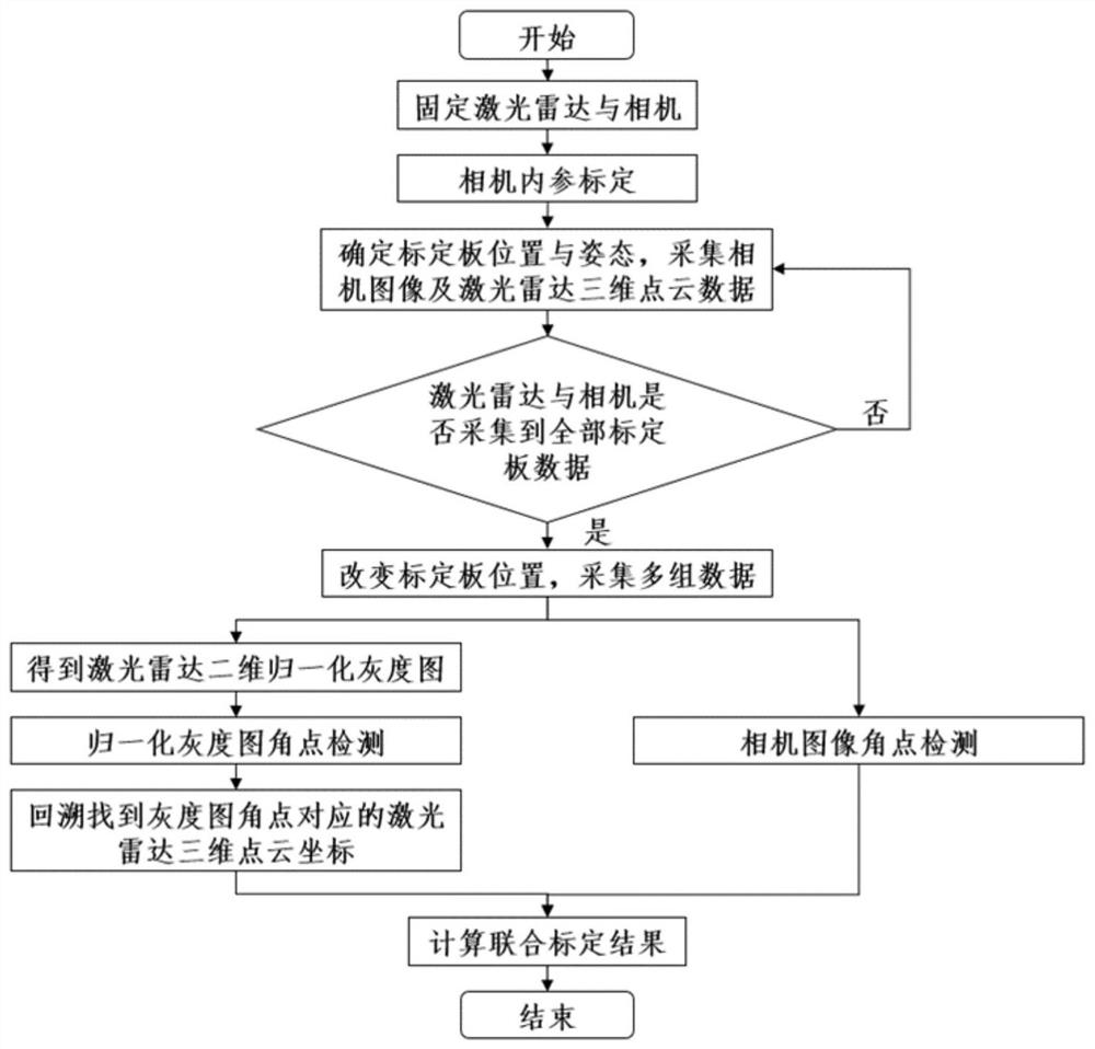
[0046]Combinefigure 1 , A laser radar is combined with the camera, the steps are as follows:

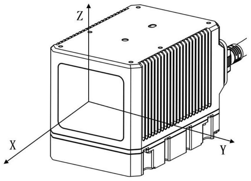
[0047]Step 1: Secure the laser radar to the same side in the same side toward the same direction, and the laser radar is in the camera-absorbing view of the camera to more than 50%.

[0048]Step 2: Calibrate the camera to get the cameraflyx, FyIndicates the camera focal length, Cx, CyIndicates the offset of the camera optical axis on the image coordinate system.

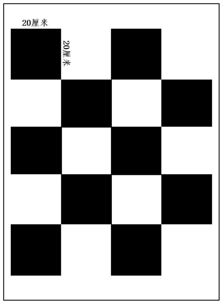
[0049]Step 3: In order to be able to fully collect the camera image and the three-dimensional point cloud data at different locations at different positions in the zone, A, B, C, D, E, F, G, H, I are selected in the combination of view. Total 9 different locations (such asFigure 4 , Arrangements in concentric circles of different radii). At each location, the camera collects one frame image data, and the laser radar collects 20 seconds three-dimensional point cloud data. Among them, the chessboard lattice usedfigure 2 As shown, in order t...


PUM


Abstract

The invention discloses a laser radar and camera combined calibration method, and the used laser radar scanning mode is non-repetitive scanning, i.e., the scanning tracks of laser radars are different each time, collection is performed for seconds in a static state, and the point cloud coverage rate in the visual field tends to be close to 100%. According to the non-repetitive scanning characteristic of the laser radar, the self-made large checkerboard calibration plates are sequentially placed at different positions in the overlapped view field of the laser radar and the camera, and the laser radar collects three-dimensional point cloud data for a long time while the camera collects a frame of image; the obtained three-dimensional point cloud data is converted into a two-dimensional normalized grey-scale map according to the point cloud intensity, corner detection is performed on the normalized grey-scale map and the camera image to obtain a corresponding two-dimensional grey-scale map and camera image corner pair, accurate three-dimensional point cloud corner coordinates are found out according to corner backtracking in the two-dimensional grey-scale map, and finally, a joint calibration result is obtained according to the corresponding three-dimensional point cloud corner points and camera image corner point coordinates, and compared with a traditional method, the method has higher precision.

Description

Technical field[0001]The present invention belongs to the field of multi-sensor data fusion, and in particular to a laser radar and a camera combined with a camera.Background technique[0002]Laser radar and camera are widely used in unmanned, intelligent robots.[0003]The advantage of laser radar is to accurately reflect the space 3D information of the environment, but in detail description, the camera cannot reflect the environmental space 3D information, but has a prominent effect in detail and color description. Therefore, in an unmanned system, it is necessary to fuse the laser radar and the camera to exhibit its own advantages. However, the premise of fusion is to combine them, and the coordinates on the space are unified. Most of the existing laser radar and camera integration methods are based on multi-wire repeat scanning laser radar. Since the product has been admitted late, the non-repetitive scanning laser radar is more involved.[0004]Open Source Automatic Driving Framework...

Claims


Application Information

Patent Timeline
IPC IPC(8): G06T7/80G06T7/13G06T5/00
CPCG06T7/80G06T2207/20164
Inventor 徐飞翔刘欢王军张文琪
Owner CHINA UNIV OF MINING & TECH
Why Eureka
Try Eureka