Automatic deicing system of camera

A camera and automatic technology, applied in the field of cameras, can solve problems such as video or image clarity degradation, the outer surface of the monitoring lens is easy to freeze, and affects the normal operation of the monitoring camera, so as to improve the accuracy and efficiency of deicing and improve the use of The effect of longevity

Inactive Publication Date: 2021-04-16
钟能俊
View PDF9 Cites 0 Cited by
  • Summary
  • Abstract
  • Description
  • Claims
  • Application Information

AI Technical Summary

Problems solved by technology

[0002] Surveillance cameras are generally installed outdoors to monitor the situation in the target area. When the outdoor temperature is below zero and it rains or the humidity is high, the outer surface of the surveillance lens is easy to freeze, resulting in clear video or images recorded by the surveillance camera. The speed drops, which seriously affects the normal operation of surveillance cameras

Method used


Image

  • Automatic deicing system of camera
  • Automatic deicing system of camera
  • Automatic deicing system of camera

Examples


Embodiment 1

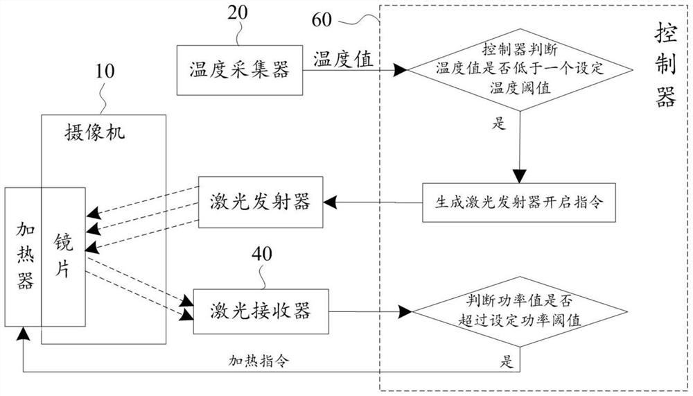
[0020] Such as figure 1 As shown, an embodiment of the present invention is an automatic deicing system for a camera, and the camera 10 includes a casing and a lens. The casing has a casing cavity, and the casing defines a lens mounting hole. The lens installation hole communicates with the housing cavity. The lens is arranged in the lens installation hole.

[0021] The automatic deicing system includes a temperature collector 20 , a laser transmitter 30 , a laser receiver 40 , a heater 50 and a controller 60 . The temperature collector 20 is arranged in the shell cavity of the casing. The temperature collector 20 has a temperature collecting terminal and a temperature value output terminal. The temperature collecting terminal is located outside the casing and can collect temperature values ​​outside the casing.

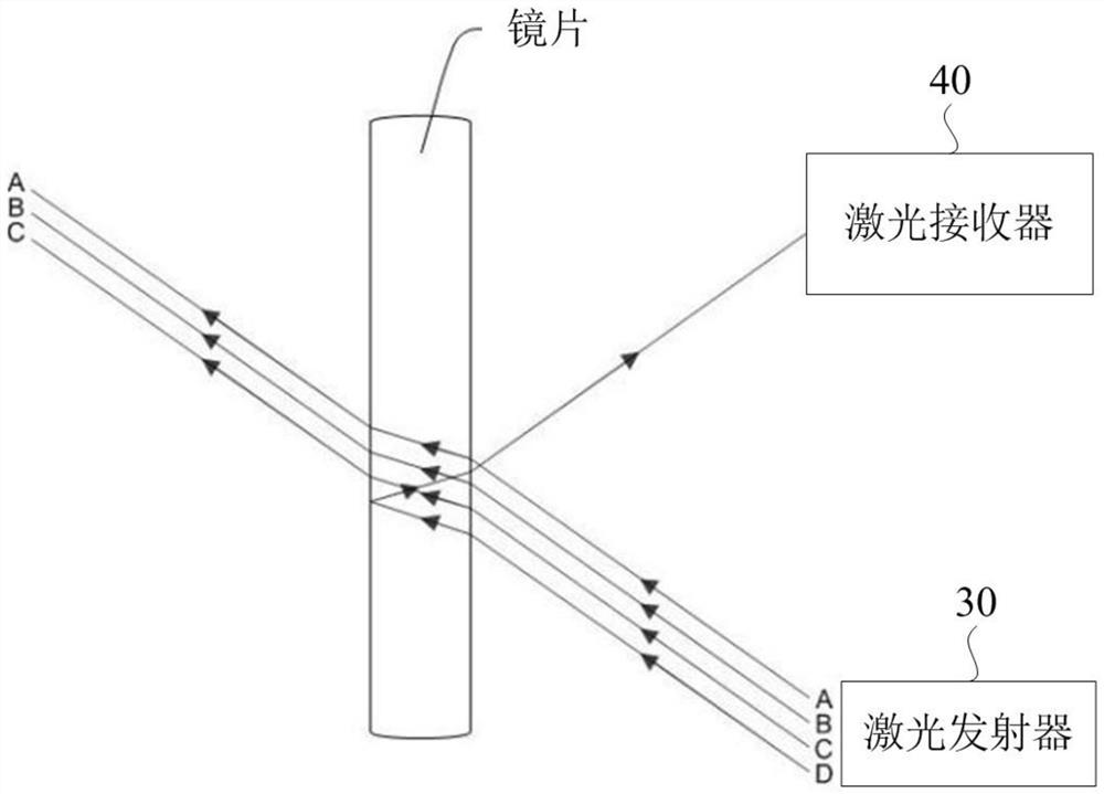
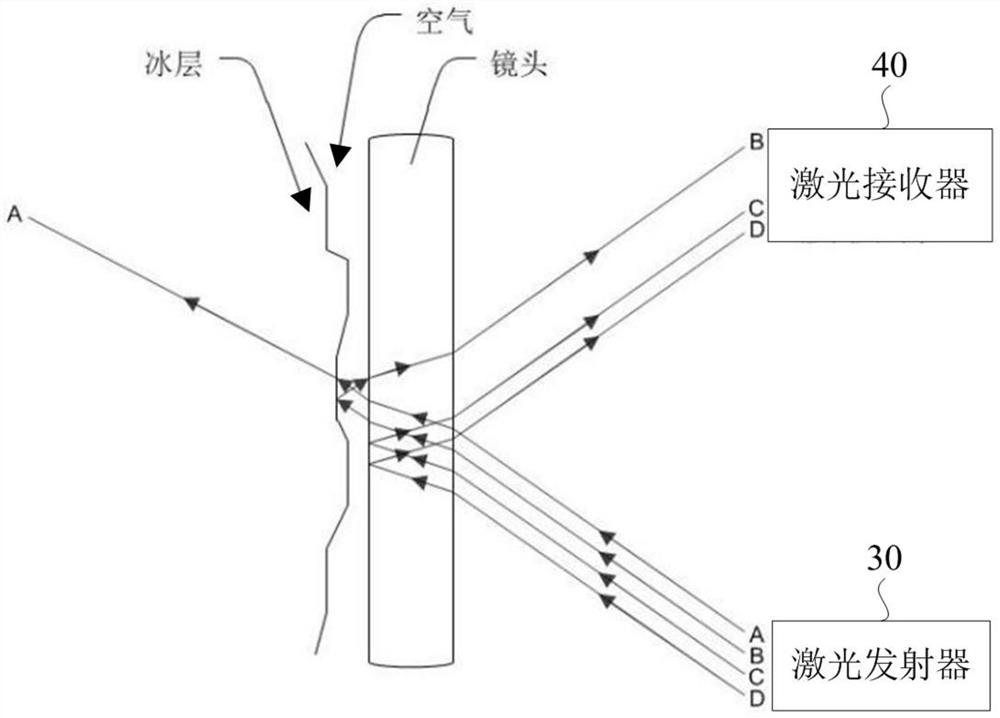
[0022] The laser emitter 30 is arranged in the shell cavity. The laser emitter 30 has a laser emitting end and a first control instruction receiving end. The lase...

Embodiment 2

[0035] Such as Figure 4 As shown, an embodiment of the present invention is an automatic deicing system for a camera, and the camera 10 includes a casing and a lens. The casing has a casing cavity, and the casing defines a lens mounting hole. The lens installation hole communicates with the housing cavity. The lens is arranged in the lens installation hole.

[0036] The camera 10 also includes a memory 13 capable of storing video data captured by the camera 10 .

[0037] The automatic deicing system includes a temperature collector 20 , a laser transmitter 30 , a laser receiver 40 , a heater 50 and a controller 60 . The temperature collector 20 is arranged in the shell cavity of the casing. The temperature collector 20 has a temperature collecting terminal and a temperature value output terminal. The temperature collecting terminal is located outside the casing and can collect temperature values ​​outside the casing.

[0038] The laser emitter 30 is arranged in the shell ...


PUM


Abstract

The invention relates to an automatic deicing system of a camera, and the system comprises the camera, a temperature collector, a laser transmitter, a laser receiver and a controller; the controller judges whether a temperature value is lower than a set temperature threshold value or not: if yes, the controller sends a starting instruction to the laser emitter, and the laser emitter is started according to the starting instruction. The controller determines whether the power value exceeds a set power threshold or not: if yes, the controller sends a heating instruction to the heater to enable the heating film to heat the lens; if not, the controller sends a heating stopping instruction to the heater to enable the heating film to stop heating the lens, so the deicing accuracy and efficiency of the existing monitoring camera are improved.

Description

technical field [0001] The invention relates to the field of cameras, in particular to an automatic deicing system for cameras. Background technique [0002] Surveillance cameras are generally installed outdoors to monitor the situation in the target area. When the outdoor temperature is below zero and it rains or the humidity is high, the outer surface of the surveillance lens is easy to freeze, resulting in clear video or images recorded by the surveillance camera. The temperature drops, seriously affecting the normal operation of surveillance cameras. Contents of the invention [0003] The object of the present invention is to provide an automatic deicing system for cameras, which can improve the deicing accuracy and efficiency of existing monitoring cameras. [0004] In order to achieve the above purpose, the technical solution adopted is: an automatic deicing system for cameras, including: [0005] A video camera includes a housing and a lens. The casing has a casi...

Claims


Application Information

Patent Timeline
Patent Type & Authority Applications(China)
IPC IPC(8): H04N5/225G03B17/55G01J1/00G05D23/19H04N7/18
Inventor 钟能俊
Owner 钟能俊
Why Eureka
Try Eureka