
Articulated shaft adjusting method for minimally invasive surgery body surface projection shaft adjustment

A minimally invasive surgery, articulated shaft technology, used in surgery, medical science, diagnosis, etc., can solve problems such as affecting the continuity of surgery and easy fatigue.

Active Publication Date: 2021-04-20
WEIHAI JINBIAN INFORMATION TECH CO LTD
View PDF7 Cites 0 Cited by
  • Summary
  • Abstract
  • Description
  • Claims
  • Application Information

AI Technical Summary

Problems solved by technology

[0007] At present, minimally invasive surgery mainly uses endoscopy, which is displayed on the monitor for doctors to observe. During observation, doctors need to constantly move their eyes at the surgical site and the monitor bracket, which affects the continuity of the operation and is prone to fatigue. In view of the above shortcomings, some researches The latter adopts the patient's body surface projection method based on augmented reality technology (Augmented Reality AR), and uses a projector to project the image captured by the endoscope on the patient's body surface, so as to assist the doctor's judgment when necessary and form a virtual epidermal transparency effect; but When doctors need large-scale observation or local observation, assistants are needed to assist in holding and adjusting body surface projection images, which will affect the continuity of surgery. For this purpose, an adjustment device for minimally invasive surgery body surface projection is provided. By detecting the doctor's leg The swing of the projection image is adjusted, and the virtual axis of human leg rotation needs to be adjusted coaxially with the hinge axis of the device during detection.

Method used


Image

  • Articulated shaft adjusting method for minimally invasive surgery body surface projection shaft adjustment
  • Articulated shaft adjusting method for minimally invasive surgery body surface projection shaft adjustment
  • Articulated shaft adjusting method for minimally invasive surgery body surface projection shaft adjustment

Examples


specific Embodiment approach 1

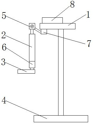
[0075] An adjustment device for body surface projection in minimally invasive surgery disclosed in this embodiment, combined with figure 1 As shown, it includes: a thigh pad 1, a calf pad 2, a foot pad 3, a base 4, a first angle sensor 5 and a second angle sensor 6, the upper end of the base 4 is provided with a supporting structure, and the supporting structure is Rods are used for support. The support structure is connected with the thigh pad 1. The thigh pad is used to provide support for the doctor's thigh. The thigh pad 1 is set horizontally, the calf pad 2 is vertically set, and one end of the thigh pad 1 It is hinged with the upper end of the calf pad 2, and the hinged rotatable surface is the first rotating surface including the length direction of the thigh pad 1 and the calf pad 2. After the doctor puts the thigh on the thigh pad, the calf It can drive the calf support plate 3 to swing in front of or to the back of the doctor. The lower end of the calf support plate ...

specific Embodiment approach 2

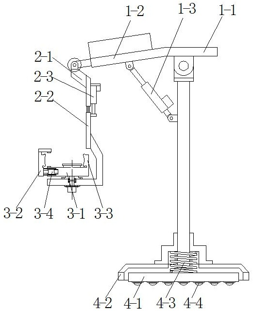
[0082] This embodiment is based on the specific implementation mode 1, specifically, in combination with figure 2 , the thigh pad 1 includes: a buttock support section 1-1, a thigh support section 1-2 and a first push rod 1-3, the support surface of the buttock support section 1-1 is arranged horizontally, and the thigh support section The support surface of 1-2 is arranged obliquely, and the lower end of the buttock support section 1-1 is hingedly connected with the support structure, the rotation surface of the hinge connection is parallel to the first rotation surface, and the first push rod 1-3 One end is hingedly connected to the support structure, and the other end of the first push rod 1-3 is hingedly connected to the lower surface of the thigh support section 1-2;

[0083] The buttock support section 1-1 supports the doctor's buttocks, and the end of the thigh support section 1-2 away from the hip support section 1-1 is inclined downward. When in use, the thigh suppor...

specific Embodiment approach 3

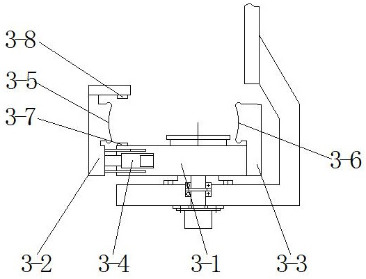
[0085] This embodiment is based on the specific implementation mode 1, specifically, in combination with figure 2 As shown, the calf pad 2 includes: an upper connection section 2-1, a lower connection section 2-2 and a second push rod 2-3, and the lower end of the upper connection section 2-1 passes along the upper connection section 2- 1 The sliding structure provided in the length direction is connected to the lower connecting section 2-2, the lower end of the lower connecting section 2-2 is provided with a horizontal section perpendicular to the length direction of the upper connecting section 2-1, and the upper surface of the horizontal section is in contact with the foot pad The plate 3 is rotationally connected, one end of the second push rod 2-3 is connected to the upper connection section 2-1, and the other end of the second push rod 2-3 is connected to the lower connection section 2-2;

[0086] The upper connecting section 2-1 and the lower connecting section 2-2 ena...


PUM


Abstract

The invention discloses an articulated shaft adjusting method for minimally invasive surgery body surface projection shaft adjustment, and belongs to the technical field of body surface projection adjustment and motion capture. According to the method, a length m is set, if c and d are different in sign, an articulated shaft is moved by one m length along a horizontal shaft, if c is a positive number and d is a negative number, the articulated shaft is moved rightwards, and if c is a negative number and d is a positive number, the articulated shaft is moved leftwards; if c and d are the same in symbol, the articulated shaft is moved by one m length along a vertical shaft, if c is a positive number and d is a positive number, the articulated shaft is moved downwards, and if c is a negative number and d is a negative number, the articulated shaft is moved upwards; and moving is stopped until the c and d symbols are the same. An axis adjustment method applied to the minimally invasive surgery body surface projection adjustment method has the advantages that the adjustment process is simple and automatic, the adjustment can be completed quickly, the adjustment time is saved, and the axis adjustment method adapts to doctors of different postures.

Description

[0001] This application is a divisional application of the invention patent application "Axis Adjustment Method Facing Minimally Invasive Surgery Body Surface Projection Adjustment Method". [0002] The original filing date: 2019-03-16. [0003] Original application number: 2019102002428. [0004] Invention name of the original application: Axis adjustment method for body surface projection adjustment method for minimally invasive surgery. technical field [0005] The invention belongs to the technical fields of body surface projection adjustment and motion capture, and in particular relates to a hinge axis adjustment method for body surface projection axis adjustment in minimally invasive surgery. Background technique [0006] Compared with traditional open surgery, minimally invasive surgery has the advantages of small wound, light pain, and fast healing, which caters to the aesthetics of modern people, so it has attracted more and more attention and is used in some abdom...

Claims


Application Information

Patent Timeline
Patent Type & Authority Applications(China)
IPC IPC(8): A61B90/00A61B90/60
Inventor 韩志勇
Owner WEIHAI JINBIAN INFORMATION TECH CO LTD
Learn More