Nozzle mounting structure with a double-cooling type height sensor for laser processing head

A technology of height sensor and laser processing head, used in laser welding equipment, metal processing equipment, manufacturing tools, etc., can solve the problem that the cooling effect may not meet the cooling requirements, cannot guarantee the height sensor cutting and anti-slag, and affect the cutting production efficiency and other problems, to achieve the effect of ensuring the induction accuracy and the integrity of the appearance, reducing the temperature, and ensuring the processing stability.

Pending Publication Date: 2021-04-20
SUZHOU QUICK LASER TECH +1
View PDF0 Cites 3 Cited by
  • Summary
  • Abstract
  • Description
  • Claims
  • Application Information

AI Technical Summary

Problems solved by technology

[0002] At present, most of the laser cutting is to melt and evaporate the workpiece through the energy released when the beam is irradiated on the surface of the workpiece. During the cutting process, the distance between the cutting nozzle and the plate needs to be controlled at a constant value, and the most critical component to achieve this purpose is the height sensor. The huge heat generated by cutting will affect the electronic components inside the sensitivity sensor. Working accuracy, because of the accuracy, the cutting effect will be unsatisfactory or the normal cutting work cannot be carried out, which will affect the cutting production efficiency; at the same time, the plate slag that appears during the cutting process will stick to the surface of the height sensor, thus affecting the positioning accuracy and damage the sensor appearance
At present, some common solutions in the market to reduce the influence of plate heat radiation on the height sensor are to increase air cooling inside the height sensor, but the cooling effect of this solution may not meet the cooling requirements, and it cannot guarantee that the height sensor is free from cutting reactions. The effect of slag

Method used


Image

  • Nozzle mounting structure with a double-cooling type height sensor for laser processing head
  • Nozzle mounting structure with a double-cooling type height sensor for laser processing head
  • Nozzle mounting structure with a double-cooling type height sensor for laser processing head

Examples


Embodiment

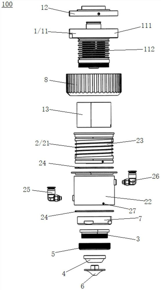
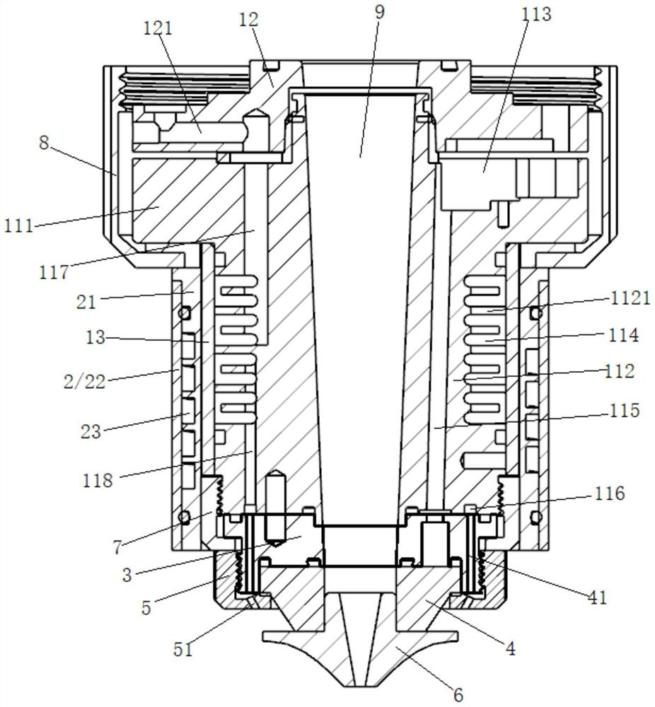
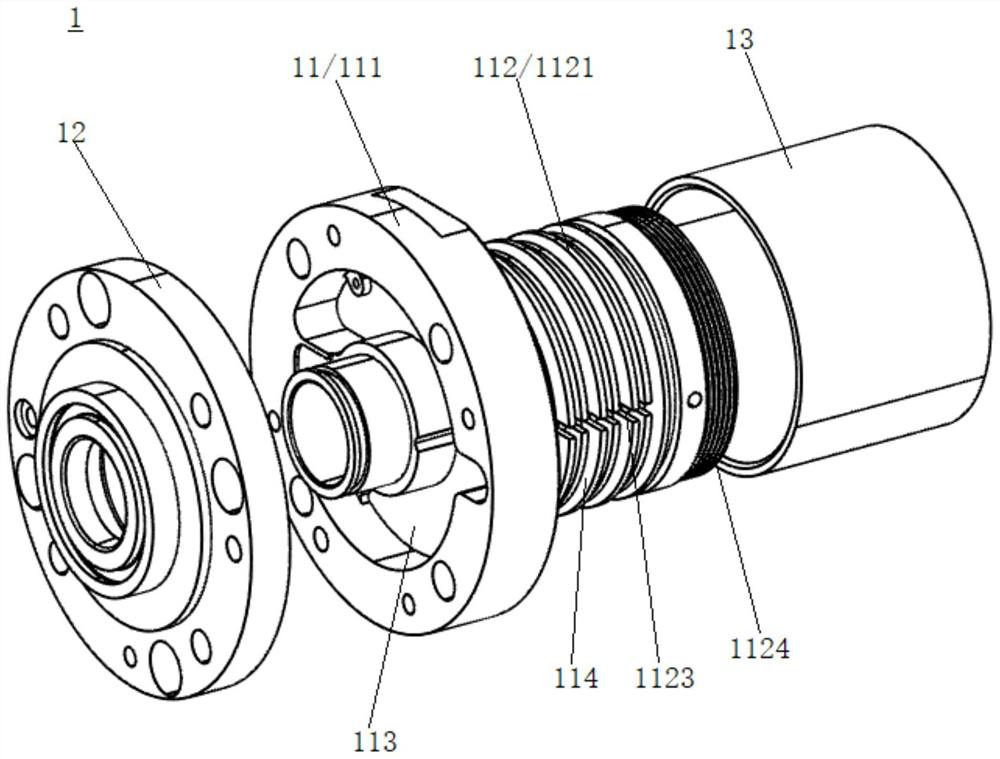
[0032] Please refer to Figure 1-Figure 8 , the present embodiment is a nozzle mounting structure 100 for a laser processing head with a double-cooled height sensor, which includes a cooling built-in height sensor 1, an outer cooling sleeve 2 that is sleeved outside the cooling built-in height sensor 1, and is arranged on the cooling The ceramic body mounting seat 3 at the bottom of the built-in height sensor 1, the mounting seat locking ring 7 that locks the ceramic body mounting seat 3 on the cooling built-in height sensor 1, and the nozzle mounting seat 4 installed on the ceramic body mounting seat 3 , the ceramic body locking ring 5 for locking the nozzle mounting seat 4 on the ceramic body mounting seat 3 , and the nozzle 6 installed on the nozzle mounting seat 4 .

[0033]The cooling built-in height sensor 1 , the ceramic mounting base 3 , the nozzle mounting base 4 and the nozzle 6 are vertically penetrated in the middle to form a laser channel 9 for the beam to pass th...


PUM


Abstract

The invention discloses a nozzle mounting structure with a double-cooling type height sensor for a laser processing head. The nozzle mounting structure comprises a cooling built-in height sensor, an outer cooling sleeve arranged outside the cooling built-in height sensor in a sleeving manner, a ceramic body mounting seat arranged at the bottom of the cooling built-in height sensor, a mounting seat locking ring for locking the ceramic body mounting seat on the cooling built-in height sensor, a nozzle mounting seat mounted on the ceramic body mounting seat, a ceramic body locking ring used for locking the nozzle mounting seat on the ceramic body mounting seat, and a nozzle mounted on the nozzle mounting seat; and the cooling built-in height sensor, the ceramic body mounting seat, the nozzle mounting seat and the middle of the whole nozzle are vertically through to form a laser channel for light beams to pass through. According to the nozzle mounting structure, the working temperature of the internal structure of the height sensor is always kept in a relatively stable range.

Description

【Technical field】 [0001] The invention belongs to the technical field of laser processing heads, and in particular relates to a nozzle mounting structure for a laser processing head with double cooling height sensors. 【Background technique】 [0002] At present, most of the laser cutting is to melt and evaporate the workpiece through the energy released when the beam is irradiated on the surface of the workpiece. During the cutting process, the distance between the cutting nozzle and the plate needs to be controlled at a constant value, and the most critical component to achieve this purpose is the height sensor. The huge heat generated by cutting will affect the electronic components inside the sensitivity sensor. Working accuracy, because of the accuracy, the cutting effect will be unsatisfactory or the normal cutting work cannot be carried out, which will affect the cutting production efficiency; at the same time, the plate slag that appears during the cutting process will...

Claims


Application Information

Patent Timeline
IPC IPC(8): B23K26/70
Inventor 黄大馆赵勇波刘德军
Owner SUZHOU QUICK LASER TECH
Why Eureka
Try Eureka