

Assembly type bridge
A prefabricated, bridge technology, applied in the direction of bridges, bridge forms, bridge parts, etc., can solve the problems of adding bridges, poor flexibility, adjusting the width of bridges and guardrails, etc.
- Summary
- Abstract
- Description
- Claims
- Application Information
AI Technical Summary
Problems solved by technology
Method used
Image

Examples
Embodiment 1
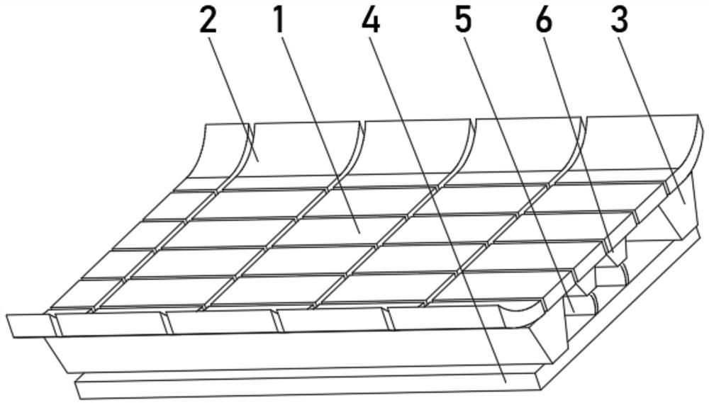
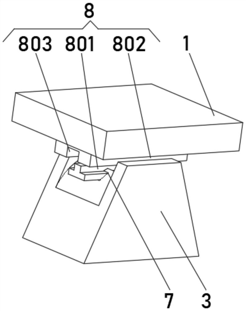
[0032] see Figure 1-2 , the present invention provides a technical solution: an assembled bridge, including a horizontal slide 1 and an elastic arc 2, the horizontal slide 1 and the elastic arc 2 are rotationally connected, and the bottom of the elastic arc 2 is equipped with side pillars 3 , the bottom of the side pillar 3 is fixedly connected with a supporting base plate 4, and the top of the supporting base plate 4 is uniformly equipped with an elastic steel plate 5, and the top of the elastic steel plate 5 is fixedly connected with a lifting pillar 6, and the tops of the side pillar 3 and the lifting pillar 6 are all opened. There is a T-shaped chute 7, and the bottoms of the horizontal slide plate 1 and the elastic arc plate 2 are equipped with a swing device 8 that is compatible with the T-shaped chute 7.
[0033] The swing device 8 includes a T-shaped slide block 801, which extends to the inside of the T-shaped chute 7 and is slidably connected with the T-shaped chute ...
Embodiment 2
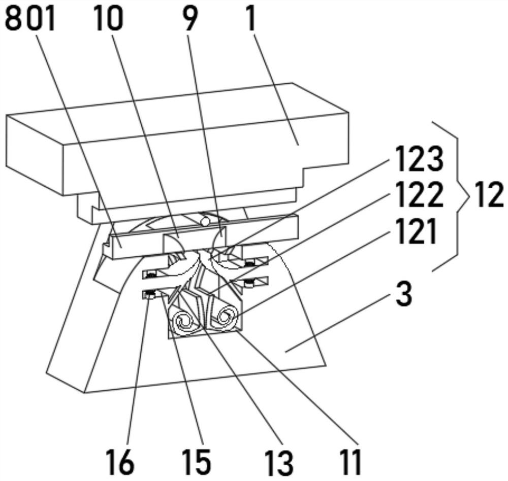
[0036] see Figure 1-3 , the present invention provides a technical solution: on the basis of Embodiment 1, a block groove 9 is provided at the bottom of the swing device 8, and a block block 10 is slidably connected between the two sides of the inner wall of the block groove 9, and the side pillars 3 and the middle position of the top of the lifting column 6 are provided with a locking slot 11, and the inside of the locking slot 11 is equipped with a locking device 12
[0037] The clamping device 12 includes an extruding plate 121, which is an arc-shaped elastic plate, and one side of the extruding plate 121 is provided with a one-way hole 122, and both sides of the inner wall of the engaging slot 11 are fixedly connected with upward rockers 123 , the upward rocking plate 123 is an elastic plate, and one end of the upward rocking plate 123 passes through the one-way hole 122 and extends above the extrusion plate 121 .
[0038]Both sides of the inner wall of the locking groov...
Embodiment 3
[0041] see Figure 1-4 , the present invention provides a technical solution: on the basis of the second embodiment, a support rod 13 is installed at the bottom of the locking device 12, and buffer devices 14 are installed on both sides of the inner wall of the locking groove 11.
[0042] The buffer device 14 includes a longitudinal chute 141, and both sides of the inner wall of the longitudinal chute 141 are provided with limiting grooves 142, and one side of the inner wall of the limiting groove 142 is rotatably connected with a stop plate 143, and a lifting block is installed inside the longitudinal chute 141. 144 , both sides of the lifting block 144 are fixedly connected with rubber blocks 145 , and the rubber blocks 145 are slidably connected with the stop plate 143 .
[0043] The stop plate 143 includes a rotating shaft a1, one end of the rotating shaft a1 is connected with a swing plate a2, the end of the swing plate a2 away from the rotating shaft a1 is fixedly connec...
PUM
 Abstract
Description
Claims
Application Information