Hydraulic engineering chute structure

A technology for water conservancy engineering and rapid flow tank, which is applied in the field of rapid flow tank, can solve the problems of simple structure of rapid flow tank, blockage of competing flow tank, single function, etc., and achieves the effect of ingenious design and ingenious structure design.

Active Publication Date: 2021-04-20
青岛金州水利勘测设计院有限公司
View PDF6 Cites 1 Cited by
  • Summary
  • Abstract
  • Description
  • Claims
  • Application Information

AI Technical Summary

Problems solved by technology

[0003]The existing rush chute has a simple structure and a single function. There will be a lot of impurities in the flood discharge flow, which will not be cleaned up in time, which will easily lead to the blockage of the rush chute and discharge The influx of a large amount of impurities into the farmland will also cause farmland pollution, so it is necessary to design a more reasonable rapid flow tank to solve this problem

Method used


Image

  • Hydraulic engineering chute structure
  • Hydraulic engineering chute structure
  • Hydraulic engineering chute structure

Examples


Embodiment Construction

[0033] The following is a clear and complete description of the technical solution of the patent of the present invention in conjunction with the accompanying drawings. Apparently, the described embodiments are part of the embodiments of the present invention, not all of them. Based on the embodiments of the present invention, all other embodiments obtained by those skilled in the art without creative efforts fall within the protection scope of the present invention.

[0034] In the description of the present invention, it should be noted that if the terms "center", "upper", "lower", "left", "right", "vertical", "horizontal", "inner", "outer" appear The orientation or positional relationship indicated by etc. is based on the orientation or positional relationship shown in the drawings, and is only for the convenience of describing the present invention and simplifying the description, rather than indicating or implying that the referred device or element must have a specific or...


PUM


Abstract

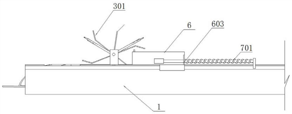
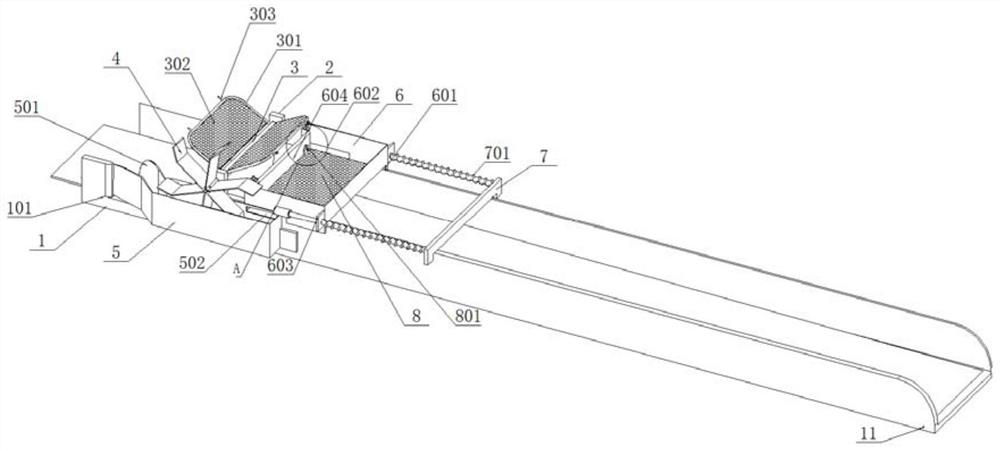
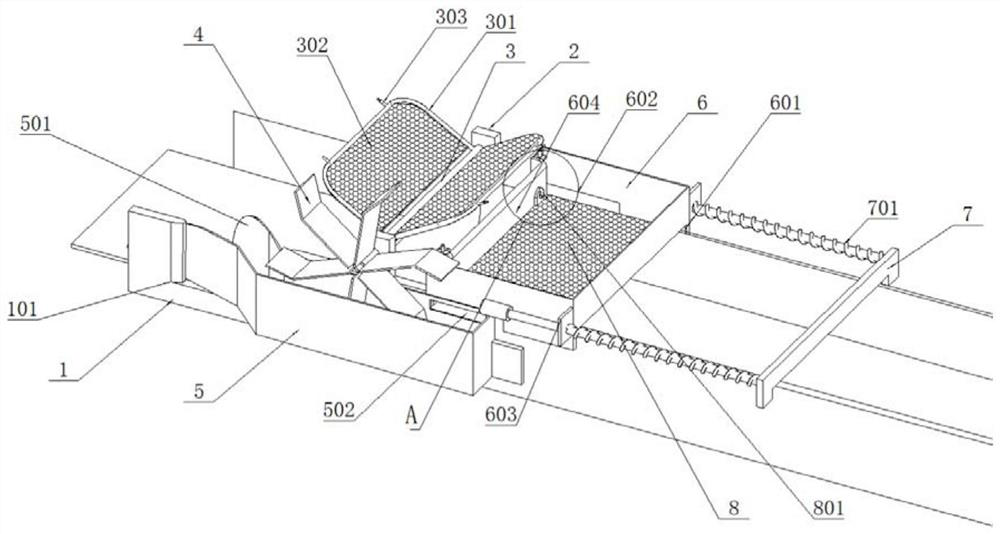
The invention discloses a hydraulic engineering chute structure. The hydraulic engineering chute structure comprises a main gutter and a material receiving cabin, a bearing seat is welded to the top of the main gutter, a stirring shaft is arranged at the top of the main gutter through the bearing seat, a salvaging frame is arranged on the stirring shaft, a filter plate is arranged on the inner side of the salvaging frame, a notch gutter is formed in the front side of the main gutter, and a secondary gutter is formed in the notch gutter, a trumpet-shaped opening extends into the main gutter from the notch gutter, and an overflow gutter is in communication with the main gutter; and an impeller is installed on the front side of the stirring shaft and located in the secondary gutter, the salvaging frame on the inner side of the stirring shaft is forced to stir and rotate in the main gutter, the material receiving bin corresponding to the salvaging frame is further arranged at the top of the main gutter, a material turning plate is arranged at the bottom of the material receiving bin, a lifting plate used for driving the material turning plate to turn is arranged on the inner wall of the main gutter, when the salvaging frame throws the intercepted impurities into the material receiving bin, the material receiving bin can be driven to slide rightwards, the material turning plate is forced to discharge the impurities thrown into the material receiving bin outwards under the influence of the lifting plate in the sliding process, the purposes of salvaging and collecting the impurities and discharging the impurities in a turning mode at the same time are achieved, and the structural design is ingenious.

Description

technical field [0001] The invention relates to the technical field of jet channels, in particular to a jet channel structure of a water conservancy project. Background technique [0002] During the construction of the drainage channel, it is necessary to add a rapid flow channel at the outlet for flood discharge and drainage. The rapid flow channel is generally added outside the discharge gate. When the gate is opened, the water stored in the embankment will be discharged outward, or used for flood discharge. Or for farmland irrigation. [0003] The existing rush trough has a simple structure and a single function. There will be a large amount of impurities in the flood discharge flow, which will not be cleaned up in a timely manner, which will easily lead to blockage of the flow trough, and the influx of a large amount of impurities discharged into the farmland will also cause farmland pollution. Therefore, it is necessary to design A more reasonable rapid trough to solve...

Claims


Application Information

Patent Timeline
Patent Type & Authority Applications(China)
IPC IPC(8): E02B8/02E02B8/06E02B15/10B08B7/02
CPCY02E10/20
Inventor 陈月红程博
Owner 青岛金州水利勘测设计院有限公司
Why Eureka
Try Eureka