
Installation method of corrugated steel plate composite wall structure system

A technology of corrugated steel plate and installation method, which is applied in the direction of walls, building components, building structures, etc., can solve the problems of difficult construction, large amount of welding at the connection site, and high overall cost

Inactive Publication Date: 2021-04-20
TONGJI UNIV
View PDF6 Cites 0 Cited by
  • Summary
  • Abstract
  • Description
  • Claims
  • Application Information

AI Technical Summary

Problems solved by technology

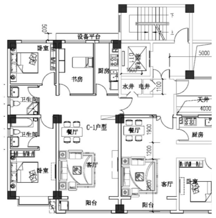
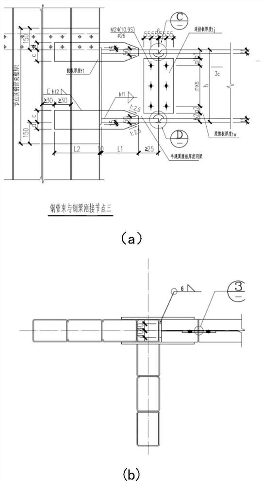
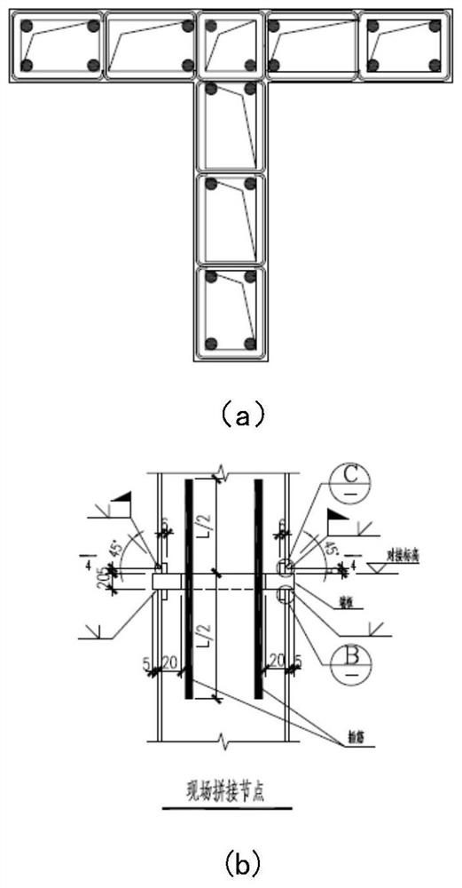
[0008] above figure 1 , figure 2 , image 3 As shown, based on the components, node structure and corresponding construction process of the shear wall structure system, practice shows that although the above shear wall structure system can well meet the needs of high-rise residential buildings with flexible planes, However, the prefabricated steel-concrete composite shear wall structure system: the structure of the rigidly connected joints between the beam and the shear wall is complex, and the vertical components The large amount of welding at the connection site and the large fireproof coating area of ​​the shear wall lead to problems such as large steel consumption, difficult construction, and high overall cost. These problems severely limit the application of prefabricated steel-concrete composite structural systems in residential buildings
Due to the above problems, there is a bottleneck, which affects the promotion and application

Method used


Image

  • Installation method of corrugated steel plate composite wall structure system
  • Installation method of corrugated steel plate composite wall structure system
  • Installation method of corrugated steel plate composite wall structure system

Examples


Embodiment 1

[0070] A corrugated steel composite wall structure system suitable for steel structure residences, characterized in that, the principle: design a new type of corrugated steel composite wall as a side-resistant component unit, by adopting the design idea of ​​​​separating the side-resistant and load-bearing components of the structural system, according to the building Functional requirements, arrange sufficient and appropriate cross-sectional shapes at appropriate locations Corrugated steel composite wall anti-side member (referred to as Anti-side member elements, Figure 4 ); the anti-side member units are connected by hinged steel beams in the horizontal direction, and the anti-side member units are connected by joints in the vertical direction, thus forming a new structural system. At the same time, the overall analysis of the new structural system is carried out, and the corrugated steel plate composite wall and hinged steel beams are designed according to the results...

Embodiment 2

[0087] Based on Embodiment 1, a set of design methods for realizing the structural system is further disclosed.

[0088] Such as Figure 10 As shown, the design method of the corrugated steel composite wall structure system includes the following steps in sequence:

[0089] S1 First, obtain the possible arrangement positions of corrugated steel plate composite walls and hinged steel beams according to the building layout drawings;

[0090] According to the specific building layout, select side-resistant member units with different cross-sections such as in-line, L-shaped, T-shaped, Z-shaped, and cross-shaped, which are suitable for actual needs. The walls are connected by hinged steel beams (6-1) .

[0091]When conditions permit, energy-dissipating combined limb walls (cylinders) (5) with greater lateral stiffness can be arranged in conjunction with stairwells, elevators, etc., and energy-dissipating connecting beams (6-2) can be used to connect. When an earthquake occurs...

Embodiment 3

[0097] Based on the design operation method of Embodiment 2, this embodiment envisages the development of a set of application software for designing and outputting construction system cases.

[0098] For example and not limitation, the application software includes building databases, including prefabricated three types of splicing structure models, including prefabricated cross-sections with different straight, L-shaped, T-shaped, Z-shaped, and cross-shaped anti-side member unit modules; application software algorithms The process is:

[0099] Step 1. Input the electronic drawings of the building layout, and obtain the possible arrangement positions of corrugated steel plate composite walls and hinged steel beams in the plan space, and provide step 2 after screening;

[0100] Step 2. Model and analyze the structure

[0101] In the analysis model, the corrugated steel plate composite wall is analyzed as a square steel pipe-corrugated steel plate-concrete composite structure ...


PUM


Abstract

The invention provides an installation method of a corrugated steel plate composite wall structure system. The installation method comprises the steps that 1, a corrugated steel plate composite wall is installed, specifically, S1-4, concrete pouring is conducted on a connecting area and the interior of a rectangular steel pipe through a grouting opening, and installation of the corrugated steel plate composite wall is completed; 2, a steel beam is installed, specifically, S2-1, a hinged steel beam needing to be connected to the composite wall is hoisted to a designated installation position, and S2-2, a steel beam web and a connecting plate welded to the rectangular steel pipe of the corrugated steel plate composite wall in advance are connected through high-strength bolts, so that connection between the hinged steel beam and the composite wall is completed; and 3, a floor slab is installed, specifically, S3-1, a prefabricated part of the floor slab is hoisted to the designated installation position to be installed, the position connected with the steel beam is placed on a flange of the hinged steel beam, and the position connected with the composite wall is placed on a pre-welded L-shaped connecting piece; and S3-2, after the prefabricated part of the floor slab is installed, concrete pouring is conducted on the whole floor slab, a cast-in-place part of the floor slab is formed, and installation of the complete floor slab is completed.

Description

technical field [0001] The invention relates to the technical field of structural engineering. Background technique [0002] Steel structures have been widely used in developed countries such as the United States, Japan, and the United Kingdom because of their advantages such as light weight, high strength, good earthquake resistance, factory production, fast construction speed, and recyclable materials. It accounts for more than 40% of the total construction, while the proportion of steel structure buildings in my country is less than 5%. [0003] The prefabricated steel-concrete composite structure residence has the advantages of high degree of industrialization, good quality, short construction period, good seismic performance, and high comprehensive technical and economic indicators. It is one of the prefabricated building systems supported by the state. Existing multi-story prefabricated steel-concrete composite structures can generally be divided into steel-concrete co...

Claims


Application Information

Patent Timeline
IPC IPC(8): E04B2/56E04G21/14
Inventor 李国强陈琛刘青罗金辉
Owner TONGJI UNIV
Learn More