A method for cleaning shaft furnace burner clogging

A cleaning method and technology for shaft furnaces, which are applied to furnaces, vertical furnaces, furnace types, etc., can solve the problems of impossible elimination of moisture and volatile impurities, large cleaning workload, and burner damage due to bumping, so as to achieve simple and convenient cleaning. , Less cleaning time, reducing the effect of burner sticking impurities

Active Publication Date: 2022-06-07
武安市裕华钢铁有限公司
View PDF8 Cites 0 Cited by
  • Summary
  • Abstract
  • Description
  • Claims
  • Application Information

AI Technical Summary

Problems solved by technology

[0003] The traditional cleaning method is to stop the furnace to extinguish the fire. After the shaft furnace cools down, remove the burners, clean them with tools, reinstall the burners and resume production. The fastest cleaning time will take more than 3 hours, and 4 burners need 8 maintenance personnel. The workers and 8 workers at the same time worked together. Through analysis and demonstration, it is impossible to eliminate the moisture and volatile impurities in the gas. The shaft furnace is at the end of the gas pipeline network. The gas temperature is low and the gas moisture is high. The current situation is not easy to change , we can only find a cleaning method with a shorter processing time to reduce the impact on the production of the shaft furnace
[0004] However, the above-mentioned existing technical solutions still have the following defects. The cleaning time is relatively long, and the cleaning workload is relatively large. At the same time, it consumes a lot of manpower. During the cleaning process, the burner is more likely to be bumped and damaged, and the practicability is poor.

Method used


Image

  • A method for cleaning shaft furnace burner clogging
  • A method for cleaning shaft furnace burner clogging
  • A method for cleaning shaft furnace burner clogging

Examples


Embodiment

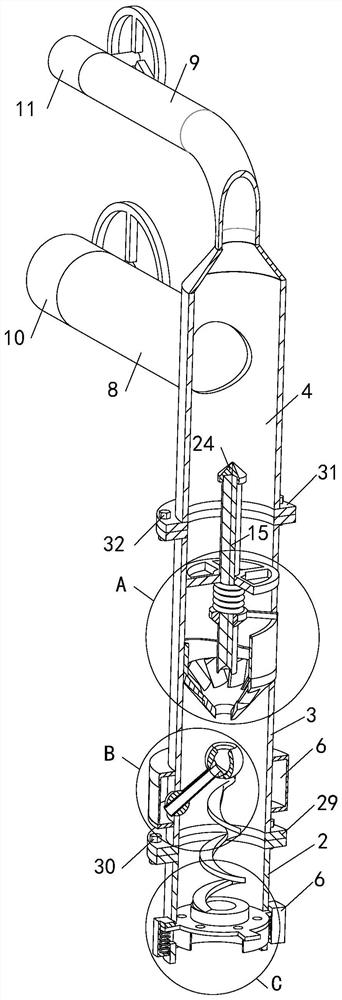
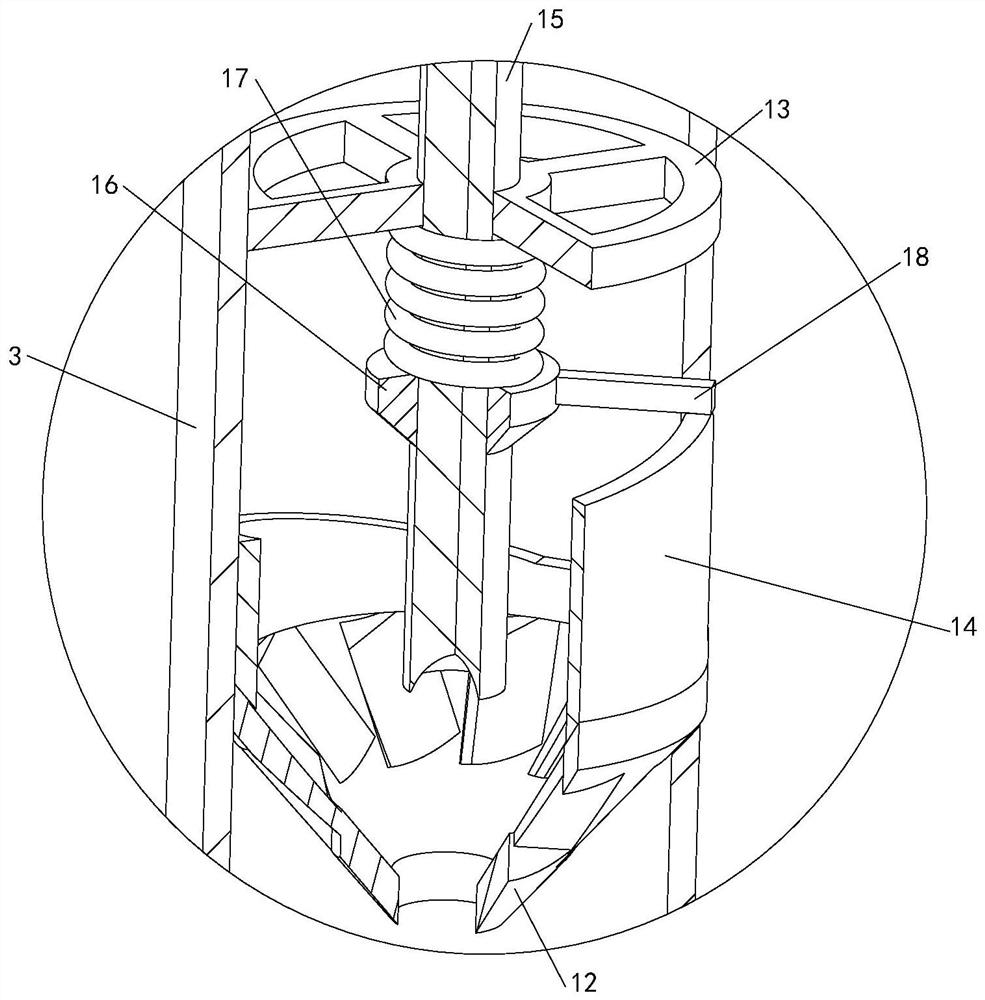
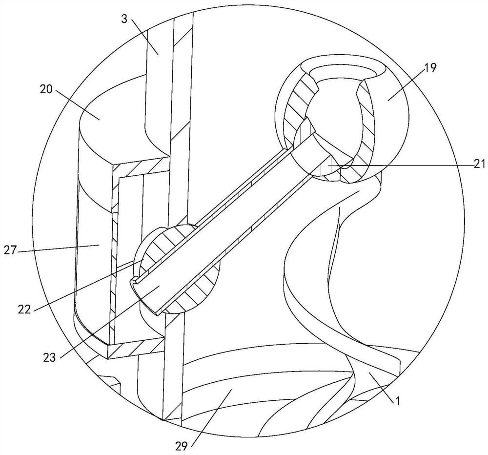
[0034] See Figure 1-8, a cleaning method of the vertical furnace burner blockage, the cleaning method of the vertical furnace burner blockage is based on a vertical furnace burner device to achieve, comprising a burner 1, further comprising a flame cylinder 2, an installation cylinder 3 and a gas supply cylinder 4, a flame cylinder 2 is connected to the mounting cylinder 3, a gas supply cylinder 4 is connected to the mounting cylinder 3, and the gas supply cylinder 4 is connected to the flame cylinder 2 by the mounting cylinder 3, the flame cylinder 2 is connected with a round fin 5, and the flame cylinder 2 is externally fixed to have multiple ear cups that match the round fin 5, Multiple ear cups 6 and round fin 5 are fixed connection elastic spring 7, burner 1 and round fin 5 connected, mounting cylinder 3 is installed with ash suppression mechanism, easy to burner 1 of the impact vibration, thereby facilitating the reduction of burner 1 adhesion impurities, and thus easy to av...


PUM


Abstract

The invention relates to the technical field of shaft furnace burner cleaning, in particular to a method for cleaning shaft furnace burner clogging, which includes a burner, a flame cylinder, an installation cylinder and an air supply cylinder, the flame cylinder is connected with the installation cylinder, and the gas supply cylinder is connected with the installation cylinder. The air supply tube is connected with the flame tube through the installation tube. There are round fins connected inside the flame tube, and a plurality of earmuffs matching the round fins are fixedly connected outside the flame tube. Between the multiple earmuffs and the round fins There are elastic springs fixedly connected between them, the burner is connected with the round fins, the ash knocking mechanism is installed in the installation cylinder, the buffer ash receiving mechanism is installed on the installation cylinder, the combustion air pipe and the gas pipe are connected to the air supply cylinder, and the combustion air pipe Combustion-supporting air gate valve and gas gate valve are respectively installed on the upper and gas pipes, which are more convenient to clean and take less time to clean, and the burner has less sticky impurities, is not easy to block, and is more stable in use. At the same time, large-scale impurities in the gas are easier to discharge , the use of cleanliness is better, more practical.

Description

Technical field [0001] The present invention relates to the field of vertical furnace burner cleaning technology, specifically a cleaning method for clogging the vertical furnace burner. Background [0002] As we all know, the vertical furnace production is the use of gas with high pressure combustion air through the vortex ring seam type burner in the combustion chamber to heat the roasting pellet, gas inevitably carries some impurities, as well as water vapor and gasified hydrocarbons and other impurities, after the gas pipeline transport cooling, with impurities of condensate along the burner into the combustion chamber after heating evaporation, because the size of the ring joint of the burner is small, some impurities bonded to the ring seam, long-term accumulation is more likely to form scaling and thus block the ring seam, Causing the amount of gas and combustion air volume to decrease and even the wind-coal ratio imbalance, seriously affecting the output and quality of th...

Claims


Application Information

Patent Timeline
Patent Type & Authority Patents(China)
IPC IPC(8): F27B1/10F27D25/00
CPCY02E20/34
Inventor 张国华胡兵武李艳华孔东亮苗金华
Owner 武安市裕华钢铁有限公司
Why Eureka
Try Eureka