Building airtight performance and noise testing instrument

A technology for testing instruments and buildings, which is applied in the field of building airtight performance and noise testing instruments, which can solve the problems of inconvenient portability and cumbersome operation, and achieve the effects of convenient handling, simple operation and convenient use

Inactive Publication Date: 2021-04-20
赵初凤
View PDF0 Cites 0 Cited by
  • Summary
  • Abstract
  • Description
  • Claims
  • Application Information

AI Technical Summary

Problems solved by technology

[0004] The purpose of the present invention is: in order to solve the existing problem that only one direction and azimuth can be detected when the air tightness and noise detection are carried out in the building room, the operation is cumbersome, and the whole room cannot be detected, and it is not easy to carry Shortcomings, and proposed a building airtight performance and noise testing instrument

Method used


Image

  • Building airtight performance and noise testing instrument
  • Building airtight performance and noise testing instrument
  • Building airtight performance and noise testing instrument

Examples


Embodiment 1

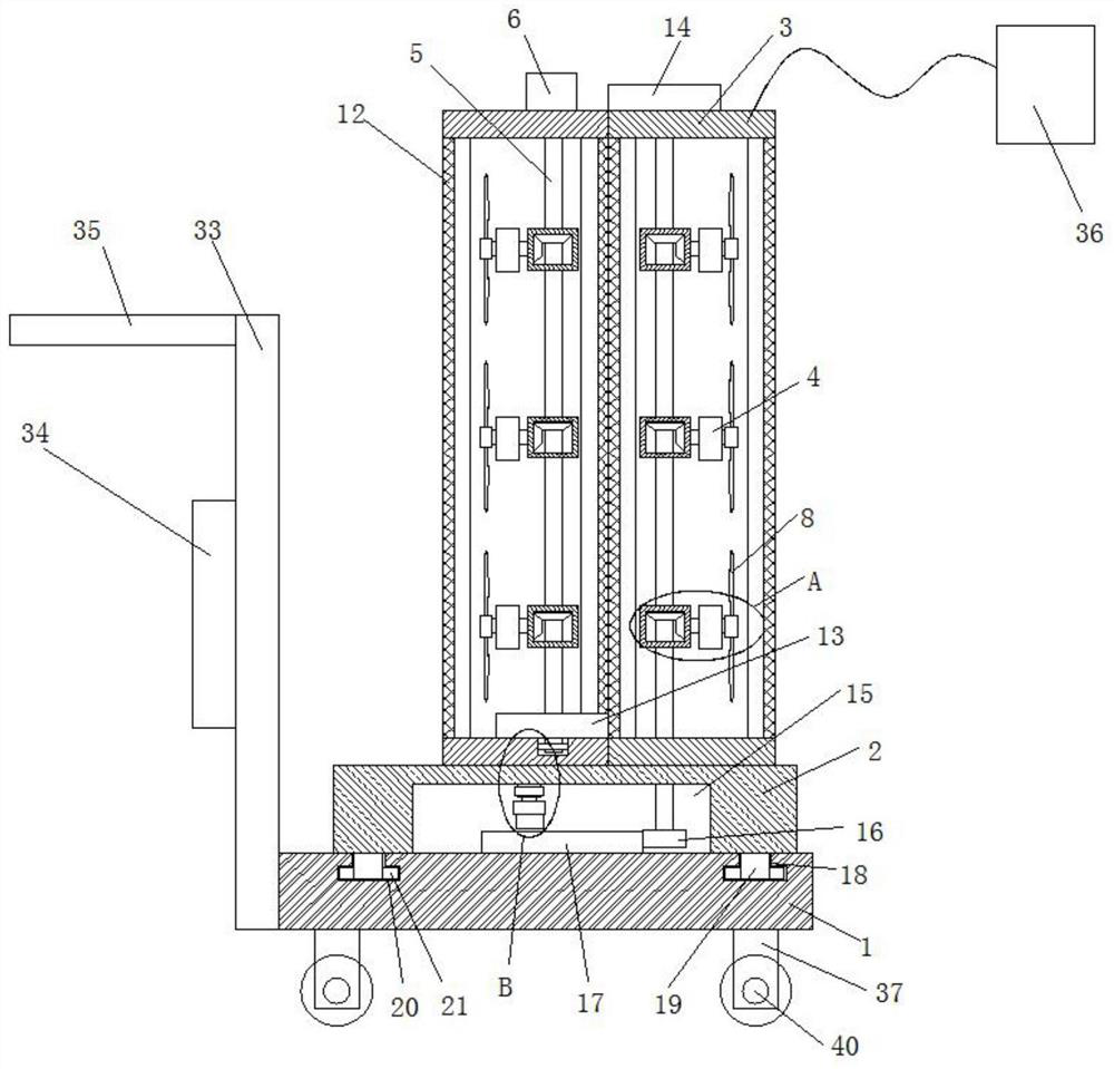
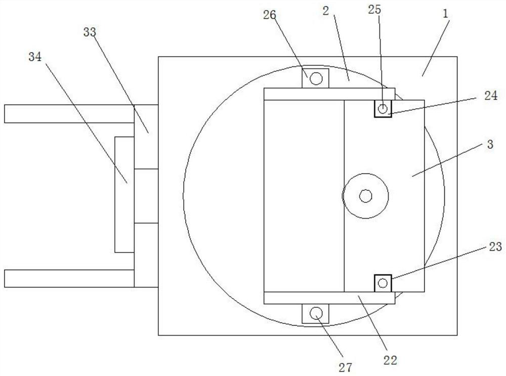
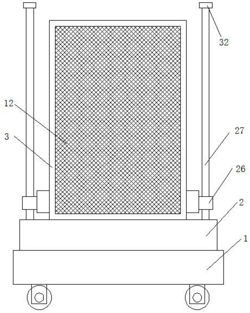
[0028] Please refer to Figure 1-Figure 5 , a building airtight performance and noise testing instrument, comprising a base 1, the top of the base 1 is rotatably connected with a placement plate 2, the top of the placement plate 2 is provided with two symmetrically arranged housings 3, and the two housings 3 The bottom of a casing 3 is fixedly connected to the placement plate 2, and a plurality of fixed rods 4 are fixedly installed on the inner wall of the casing 3, and a rotating shaft 7 is rotatably connected to the fixed rod 4, and a fan blade 8 is fixedly installed on one end of the rotating shaft 7, Both sides of the casing 3 are provided with openings, and a filter plate 12 is fixedly installed on the opening, and a transmission rod 5 is rotatably connected to the inner wall of the casing 3, and the transmission rod 5 is connected to the rotating shaft 7 in transmission. A first motor 6 is fixedly installed on the top of the housing 3, the output shaft of the first motor...

Embodiment 2

[0039] Please refer to Figure 1-Figure 5 , a building airtight performance and noise testing instrument, comprising a base 1, the top of the base 1 is rotatably connected with a placement plate 2, the top of the placement plate 2 is provided with two symmetrically arranged housings 3, and the two housings 3 The bottom of a casing 3 is fixedly connected with the placement plate 2, and a plurality of fixed rods 4 are welded on the inner wall of the casing 3, and a rotating shaft 7 is connected to the fixed rods 4, and a fan blade 8 is welded on one end of the rotating shaft 7. Both sides of 3 are provided with openings, and a filter plate 12 is welded on the opening, and a transmission rod 5 is rotatably connected to the inner wall of the housing 3, and the transmission rod 5 is connected to the rotating shaft 7 in transmission, and one of the two housings 3 3 The top of the top is fixed with a first motor 6 by bolts, the output shaft of the first motor 6 is fixedly connected w...


PUM


Abstract

The invention relates to a building airtight performance and noise testing instrument comprising a base, the top of the base is rotatably connected with a placing plate, the top of the placing plate is provided with two symmetrically arranged shells, the bottom of one of the two shells is fixedly connected with the placing plate, and the inner wall of the shell is fixedly provided with a plurality of fixing rods. A rotating shaft is rotatably connected to each fixing rod, fan blades are fixedly installed at one end of the rotating shaft, openings are formed in the two sides of each shell, filtering plates are fixedly installed on the openings, a transmission rod is rotatably connected to the inner wall of each shell, the transmission rod is in transmission connection with the rotating shaft, and a first motor is fixedly installed at the top of one of the two shells; and output shafts of the first motors are fixedly connected with the corresponding transmission rods. The instrument is easy to operate and convenient to use, people can carry the instrument conveniently, meanwhile, all-around air blowing can be conducted indoors, and then indoor air tightness and noise can be detected conveniently.

Description

technical field [0001] The invention relates to the technical field of testing instruments, in particular to a building airtight performance and noise testing instrument. Background technique [0002] The airtight performance of building rooms has a significant impact on building energy consumption. Relevant studies have shown that in heating buildings in northern my country, the building energy consumption generated by the infiltration of room air cold air accounts for about 1 / 3 to 1 / 4 of the total building energy consumption. As the thermal insulation of building rooms continues to improve, the importance of airtightness becomes even more pronounced. Therefore, improving the airtightness of building rooms can greatly reduce the loss of building energy consumption caused by the infiltration of cold air, which is of great significance for reducing building energy consumption. [0003] Existing air tightness and noise detection in the building room can only be detected in o...

Claims


Application Information

Patent Timeline
Patent Type & Authority Applications(China)
IPC IPC(8): G01M3/02G01H17/00G01N29/04G01N29/22
Inventor 赵初凤
Owner 赵初凤
Why Eureka
Try Eureka