Method for generating Marangoni effect

A Marangoni effect technology, applied in the field of Marangoni effect, can solve the problem of limiting the application field of photo-induced Marangoni effect to drive liquid flow, etc.

Active Publication Date: 2021-04-20
UNIV OF ELECTRONIC SCI & TECH OF CHINA
View PDF10 Cites 3 Cited by
  • Summary
  • Abstract
  • Description
  • Claims
  • Application Information

AI Technical Summary

Problems solved by technology

The photoinduced Marangoni effect requires not only high-intensity laser light, but also localized heating of materials that can strongly absorb the incident laser light.

Method used


Image

  • Method for generating Marangoni effect
  • Method for generating Marangoni effect
  • Method for generating Marangoni effect

Examples


Embodiment 1

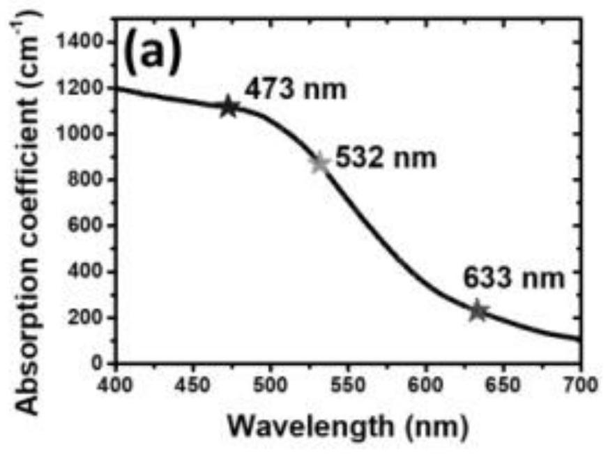
[0133] This embodiment provides an engraving method, including: 532nm continuous laser irradiating the ferrofluid, the ferrofluid absorbs energy to generate a local temperature difference, produces the Marangoni effect, and makes the ferrofluid form pits;

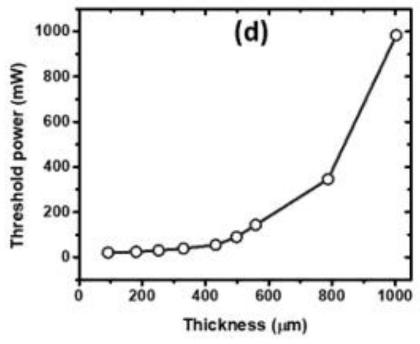
[0134] image 3 The relationship between the critical power of the 532nm continuous laser engraving and the thickness of the ferrofluid, the abscissa is the thickness of the ferrofluid, and the ordinate is the critical power of the laser.

[0135] Specific embodiment mode 1:

[0136] 1. If Figure 4 As shown in (a), an engraving method, under the irradiation of unfocused 532nm continuous laser (spot diameter is about 0.5mm, laser power 20mw), ferrofluid absorbs energy to generate local temperature difference, resulting in Marangoni effect, iron The ferrofluid deforms, forming dimples.

[0137] The thickness of the ferrofluid is 250 μm; the pit shape is circular.

[0138] The pit formation process includes:

[0139] (1)...

specific Embodiment approach 3

[0172] Such as Figure 5 As shown in (a), use a focused 532nm red commercial laser pointer to produce a red laser beam to irradiate the ferrofluid, which produces the Marangoni effect, and pits are formed on the surface of the ferrofluid; the shape of the pits is a character; the ferrofluid The thickness is 25μm;

[0173] Adjust the laser power according to the relationship between the critical power and the thickness of the ferrofluid.

[0174] The bottom area of ​​ferrofluid is 2375mm 2 In the petri dish, a magnetic bar is arranged below the petri dish.

[0175] Text engraved with a red laser beam can be easily erased by sliding the magnetic stick under the Petri dish;

[0176] Figure 5 (a1)-(a5) are images of characters U, E, S, T, and C engraved by the red laser beam.

specific Embodiment approach 4

[0178] Such as Image 6 Shown in (a), the 532nm green laser beam of focusing produces Marangoni effect on the irradiation ferrofluid thin film, makes ferrofluid surface form pit; Described pit shape is literal; The thickness of ferrofluid film is 250μm;

[0179] Adjust the laser power according to the relationship between the critical power and the thickness of the ferrofluid.

[0180] The bottom area of ​​ferrofluid is 2375mm 2 In the petri dish, a magnetic bar is arranged below the petri dish.

[0181] Text engraved with a green laser beam can be easily erased by sliding the magnetic stick under the Petri dish;

[0182] Text engraved with a green laser beam can be easily erased by sliding a magnetic stick under the substrate;

[0183] Image 6 (a1)-(a5) are pictures of characters U, E, S, T, and C engraved by the green laser beam.

[0184] It can be seen from this embodiment that even if a commercial laser pointer is used, a macroscopic Marangoni effect can be generate...


PUM

PropertyMeasurementUnit
Absorption coefficientaaaaaaaaaa
Wavelengthaaaaaaaaaa
Thicknessaaaaaaaaaa

Abstract

The invention discloses a method for generating a Marangoni effect, a method for achieving engraving based on the Marangoni effect and a method for driving liquid to move. The method for generating the Marangoni effect comprises the steps that a light source is used for irradiating or a heat source is close to a solution A, the solution A absorbs energy to generate a local temperature difference, and the Marangoni effect is generated; the solution A is a solution which is strong in photo-thermal absorption and large in surface tension change coefficient along with temperature. Through holes and/or pits in various shapes can be carved, the movement direction of driving liquid can be controlled, vertical, horizontal and inclined movement can be achieved, repeatability is achieved, the application range is wide, the application potential is large, and energy efficiency conversion is high.

Description

technical field [0001] The invention relates to the technical field of light-controlled fluid movement, in particular to a method for generating the Marangoni effect. Background technique [0002] The control of liquid droplets and the study of liquid surface films by laser are excellent in non-contact, precision and instantaneous in applications such as microfluidics, physical dehumidification, welding, chemical microreactors and biological science systems. characteristics have aroused extensive interest of researchers. Light-controlled micro-liquid movement, especially the micro-liquid movement driven by photocapillary force, has aroused great research interest of researchers, because light control can achieve non-contact, instantaneous, fixed-point and precise control. Driving liquid motion with light relies on two forces: optical force and photocapillary force. When the photocapillary force drives the movement of a small amount of liquid, it does not require special op...

Claims


Application Information

Patent Timeline
IPC IPC(8): G01N13/02G03F1/68
Inventor 艾鑫王志明林峰余鹏童鑫张航
Owner UNIV OF ELECTRONIC SCI & TECH OF CHINA
Why Eureka
Try Eureka