Automatic calibration method for millimeter-wave radar and camera

A millimeter-wave radar and automatic calibration technology, applied in neural learning methods, radio wave reflection/re-radiation, radio wave measurement systems, etc., can solve the problems of complicated calibration process, camera can not directly get the actual distance, manual measurement, etc. To achieve the effect of ensuring good operation and reducing the workload of calibration

Active Publication Date: 2021-04-20
TONGJI UNIV
View PDF11 Cites 3 Cited by
  • Summary
  • Abstract
  • Description
  • Claims
  • Application Information

AI Technical Summary

Problems solved by technology

[0003] Since the camera and the millimeter-wave radar are installed in different positions of the vehicle, there are spatial differences between the referenced coordinate systems, so it is necessary to perform spatial calibration. During the calibration process, it is necessary to find multiple sets of three-dimensional coordinates of the matching points identified by the two sensors. In order to solve the spatial transformation matrix, the camera cannot directly obtain the actual distance of the target. Usually, this step requires manual measurement, which will inevitably cause inconvenience and errors. Among them, the calibration of the camera also needs to be calibrated with internal parameters to obtain the internal reference matrix. The entire calibration process is relatively complicated

Method used


Image

  • Automatic calibration method for millimeter-wave radar and camera
  • Automatic calibration method for millimeter-wave radar and camera
  • Automatic calibration method for millimeter-wave radar and camera

Examples


Embodiment

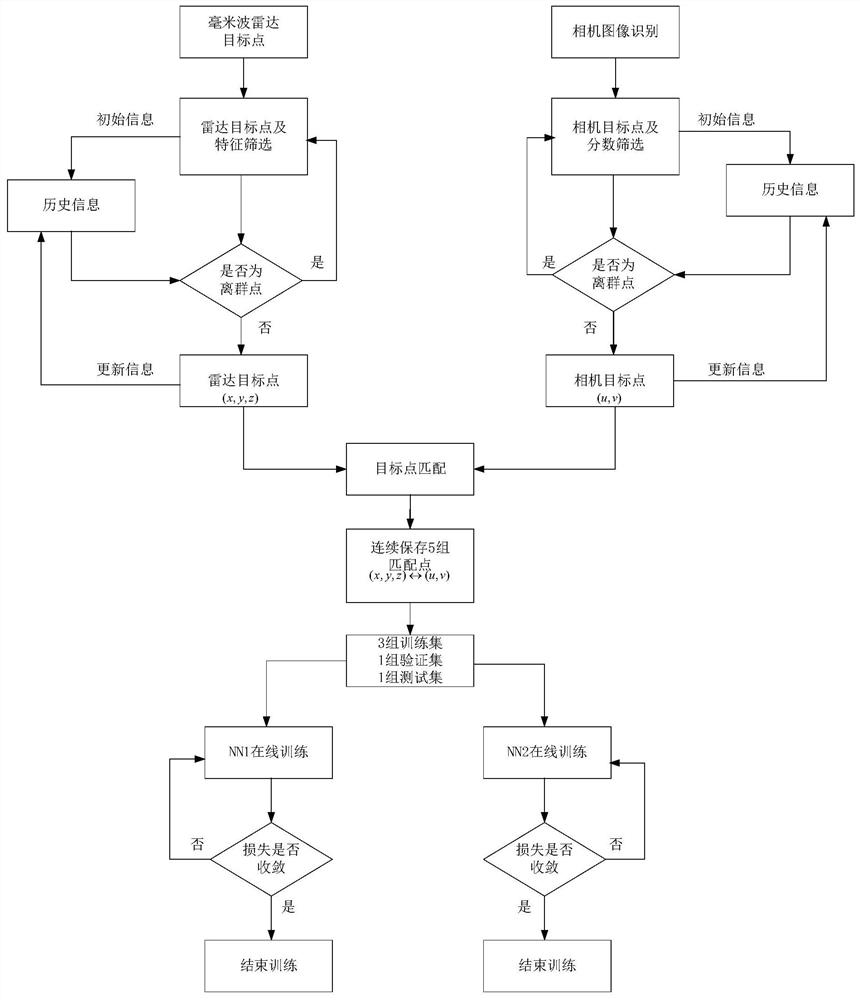
[0050] Such as figure 1 As shown, the present invention provides an automatic calibration method for a millimeter-wave radar and a camera, comprising the following steps:

[0051] S1. This method needs to be implemented in an open field to ensure that there is only one moving target within the cross-visual range of the millimeter-wave radar and the camera. The moving target needs to move as many positions as possible within the cross-visual range. Sampling is performed at the same starting time and at the same frequency. The sampling period of this embodiment is 0.08s, and calibration begins after 5 sampling periods;

[0052] S2. Use the millimeter-wave radar and camera for sampling, and obtain the coordinates of n millimeter-wave radar target points in each sampling period Coordinates of m camera target center pixel points There are many classic open source algorithms for image-based target detection. The algorithm used in this embodiment is YOLOV2, and an appropriate ima...


PUM


Abstract

The invention relates to an automatic calibration method for a millimeter-wave radar and a camera. The method comprises the following steps: 1), setting and only setting one moving target in a cross visual range of the millimeter-wave radar and the camera, wherein the moving target moves at a plurality of positions in the cross visual range; 2) performing sampling bythe millimeter-wave radar and the camera at the same starting moment and with the same frequency; 3) preliminarily screening a plurality of target points of the millimeter wave radar and the camera in each sampling period; 4) respectively obtaining target points obtained by the millimeter-wave radar and the camera in a plurality of continuous sampling periods, and carrying out outlier screening; and 5) constructing a neural network for training according to the radar target point coordinates and the camera target point coordinates in the continuous sampling period after outlier screening, and realizing automatic calibration of the millimeter-wave radar and the camera according to the trained neural network. Compared with the prior art, the method has the advantages that the calibration workload is reduced, and camera internal parameter calibration and sensor external parameter calibration are combined into a whole.

Description

technical field [0001] The invention relates to the technical field of automatic driving, in particular to an automatic calibration method for a millimeter-wave radar and a camera. Background technique [0002] With the development of driver assistance systems and automatic driving systems, the perception of the surrounding environment has changed from a single sensor to multi-sensor fusion. Cameras and millimeter-wave radars are two types of sensors commonly used today. The camera can return the outline and color information of the target, but it is not easy to obtain the position information of the target, and it will be affected by the weather. Millimeter wave radar can return the accurate position and speed information of the target, and has the characteristics of all-weather perception. Therefore, the effective use of these two sensors can further improve the perception of the whole system. [0003] Since the camera and the millimeter-wave radar are installed in diff...

Claims


Application Information

Patent Timeline
IPC IPC(8): G01S7/40G01S13/86G01S13/931G06T7/80G06N3/04G06N3/08
CPCY02A90/10
Inventor 朱元徐瑞东陆科安浩吴志红
Owner TONGJI UNIV
Why Eureka
Try Eureka