Performance calculation method, device and equipment for thermodynamic system

A technology of thermal system and calculation method, applied in calculation, instrument, data processing application, etc., can solve the problem of low accuracy of calculation results, and achieve the effect of improving calculation accuracy, ensuring output stability, and suppressing parameter fluctuations.

Pending Publication Date: 2021-04-20
华润电力技术研究院有限公司
View PDF0 Cites 0 Cited by
  • Summary
  • Abstract
  • Description
  • Claims
  • Application Information

AI Technical Summary

Problems solved by technology

[0005] The object of the present invention is to provide a performance calculation method, device, equipment and computer-readable storage medium of a thermal system, to solve the problem that the parameter obtained in the prior art is the process quantity of the control system adjusting the balance weight of the thermal system, resulting in calculation results The problem of low accuracy

Method used


Image

  • Performance calculation method, device and equipment for thermodynamic system
  • Performance calculation method, device and equipment for thermodynamic system
  • Performance calculation method, device and equipment for thermodynamic system

Examples


specific Embodiment approach

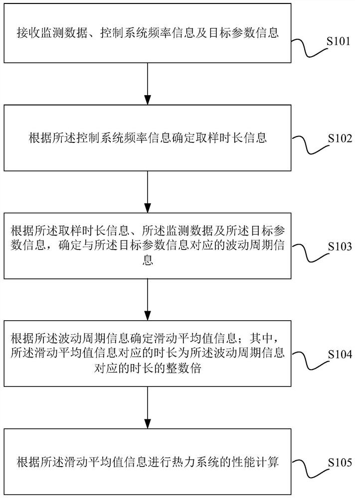
[0053] The core of the present invention is to provide a method for calculating the performance of a thermal system, and a schematic flow chart of a specific implementation thereof is as follows figure 1 As shown, it is called the first specific implementation mode, including:

[0054] S101: Receive monitoring data, control system frequency information and target parameter information.

[0055]The monitoring data refers to system parameter information that needs to be used as a criterion. Similarly, as mentioned above, the thermal system is usually controlled by multiple complex advanced control systems, and such a complex thermal system cannot maintain a static steady state, but is always in dynamic adjustment, that is, the parameters at high frequencies are too high ——Turn it down immediately, the parameter is too low——In the change of immediately increasing it, the relevant parameters will eventually change periodically, and the information reflecting the frequency of this...

Embodiment approach

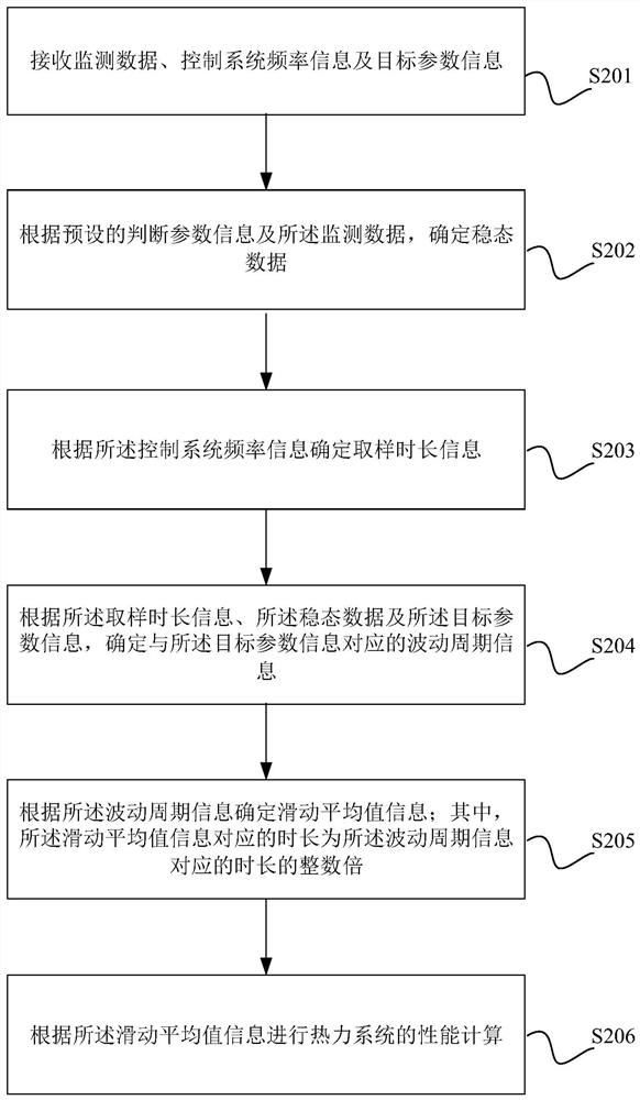
[0066] As a preferred embodiment, this step includes:

[0067] S2021: Determine a judgment parameter value corresponding to time according to the monitoring data and the judgment parameter information.

[0068] S2022: Compare the judgment parameter value with a preset steady-state judgment interval, and determine a time period in which the judgment parameter value is in the steady-state judgment interval as a steady-state time period.

[0069] S2023: Determine the steady-state data according to the steady-state time period and the monitoring data.

[0070] For example, for the "turbine speed", the preset stable interval is "150 rpm to 300 rpm", you need to exclude the time period when the speed is outside this interval, and only keep the time period when the speed is within this interval. The parameter value of the time period is used as the input quantity of the subsequent operation (that is, the steady-state data).

[0071] S203: Determine sampling duration information acc...


PUM


Abstract

The invention discloses a performance calculation method of a thermodynamic system. The method comprises the following steps: receiving monitoring data, control system frequency information and target parameter information; determining sampling duration information according to the control system frequency information; determining fluctuation period information corresponding to the target parameter information according to the sampling duration information, the monitoring data and the target parameter information, wherein the duration corresponding to the sliding average value information is integral multiples of the duration corresponding to the fluctuation period information; determining moving average value information according to the fluctuation period information; and calculating the performance of the thermodynamic system according to the moving average value information. According to the method, device and equipement, the actual parameter fluctuation problem of the thermodynamic system can be suppressed, so that the fluctuation of a performance calculation result is effectively suppressed, and the output stability is ensured. The invention further provides a performance calculation device and equipment of the thermodynamic system and a computer readable storage medium.

Description

technical field [0001] The present invention relates to the field of thermal system calculation, in particular to a thermal system performance calculation method, device, equipment and computer-readable storage medium. Background technique [0002] The performance calculation of the thermal system of the thermal power generation unit is currently based on the data collected by the thermal power plant from multiple types of sensors such as temperature, pressure, and flow distributed in different positions of the system, and the performance of the thermal power generation unit is calculated online in accordance with relevant industry or national standards. [0003] The relevant calculation methods stipulated by the industry standard or the national standard are based on the steady-state working conditions of the thermal system or a long period of time. In the actual thermal system, since the measuring points are distributed in different positions, they are adjusted by different...

Claims


Application Information

Patent Timeline
Patent Type & Authority Applications(China)
IPC IPC(8): G06Q10/06G06Q50/06
Inventor 张含智李晓静曾祥浩刘道明聂怀志袁雪峰周严伟马成龙陈建华卫平宝李烨荣智海陈木斌陈世和袁俊
Owner 华润电力技术研究院有限公司
Why Eureka
Try Eureka