Automatic exposure control system and automatic exposure control method

An automatic exposure and control system technology, applied in medical science, equipment for radiological diagnosis, diagnosis, etc., can solve problems such as high cost, large exposure error, and complex structure

Active Publication Date: 2021-04-23
SHANGHAI IRAY TECH
View PDF13 Cites 1 Cited by
  • Summary
  • Abstract
  • Description
  • Claims
  • Application Information

AI Technical Summary

Problems solved by technology

[0005] In view of the shortcomings of the prior art described above, the purpose of the present invention is to provide an automatic exposure control system and an automatic exposure control method, which are used to solve the problem of limited application scenarios, high cost, complex structure, and exposure problems of automatic exposure control in the prior art. big error

Method used


Image

  • Automatic exposure control system and automatic exposure control method
  • Automatic exposure control system and automatic exposure control method
  • Automatic exposure control system and automatic exposure control method

Examples


Embodiment 1

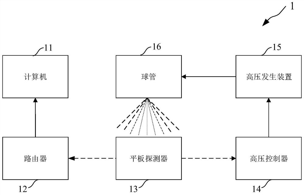
[0044] Such as Figure 1 ~ Figure 3 As shown, the present embodiment provides an automatic exposure control system 1, and the automatic exposure control system 1 includes:

[0045] Computer 11 , router 12 , flat panel detector 13 , high voltage controller 14 , high voltage generating device 15 and ball tube 16 .

[0046] Such as figure 1 As shown, the computer 11 communicates with the flat panel detector 13 through the router 12 , and the computer 11 sends control instructions to the flat panel detector 13 and receives signals collected by the flat panel detector 13 .

[0047] Specifically, in this embodiment, the computer 11 is wired or wirelessly connected to the router 12, and the router 12 is wirelessly connected to the flat panel detector 13; in actual use, the computer 11 and the router 12. The router 12 and the flat panel detector 13 can be connected in a corresponding way (wired or wireless) according to needs, which is not limited to this embodiment.

[0048] Such as...

Embodiment 2

[0062] Such as Figure 4 As shown, this embodiment provides an automatic exposure control method. In this embodiment, the automatic exposure control method is implemented based on the automatic exposure control system of Embodiment 1, and is not limited to the system of this embodiment in actual use. The automatic exposure control method includes:

[0063] 1) Turn on the flat panel detector 13, set the parameters of the flat panel detector 13, and select the exposure radiation field of the flat panel detector 13.

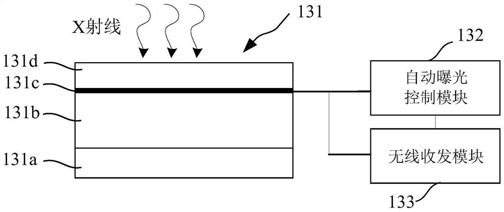
[0064] Specifically, at first the flat panel detector 13 is placed in the detection system and electrically connected with other devices in the detection system, the detection system includes but not limited to DR (Digital Radiography, direct digital X-ray), CT (computed tomography, Electronic computer tomography) and security inspection machines, any system that uses flat panel detectors for image acquisition is applicable.

[0065] Specifically, the flat panel d...

Embodiment 3

[0079] This embodiment provides an automatic exposure control method, which is different from Embodiment 2 in that the automatic exposure control method detects the exposure start moment by scanning the exposure dose of the exposure radiation field area of ​​the flat panel detector To realize automatic exposure detection, step 2) specifically includes:

[0080] In this embodiment, the exposure start time is detected by scanning the exposure dose of the exposure radiation field area of ​​the flat panel detector 13 . More specifically, after step 1) is completed, the exposure window of the flat panel detector 13 is opened to enter the automatic exposure control mode. The flat panel detector 13 enters the integration state, scans the exposure radiation field area of ​​the flat panel detector 13, obtains the exposure dose rate based on the gray value of the image in the exposure radiation field, obtains the exposure dose by integration, and exposes If the dose is greater than a p...


PUM


Abstract

The invention provides an automatic exposure control system and an automatic exposure control method. The system comprises a computer in communication with a flat panel detector through a router; the flat panel detector used for executing automatic exposure control and image acquisition and sending a switching-off control signal and acquired information; a high-voltage controller in communication with the flat panel detector and used for closing a high-voltage generating device based on the switching-off control signal; and a bulb tube for emitting X-rays based on the high-voltage signal emitted by the high-voltage generating device. According to the invention, the switching-off control signal is transmitted in a wireless manner, and application scene is not limited; automatic exposure control and real-time statistics or prediction of exposure dose at the end of exposure are realized based on exposure dose detection of an exposure irradiation radiation field area of a flat panel detector, the system has a simple structure and low cost, and can effectively avoid exposure dose errors caused by problems such as line delays; meanwhile, has advantages of short drawing cycle and low operation complexity.

Description

technical field [0001] The invention relates to the field of flat panel detection, in particular to an automatic exposure control system and an automatic exposure control method. Background technique [0002] Flat panel detector is a new type of X-ray image detection technology that was born in the last century. It is famous for its fast imaging speed and high resolution. It is widely used in medical detection, non-destructive testing, security inspection, anti-terrorism and other fields. At present, the traditional AEC (Automatic Exposure Control, automatic exposure control) uses ionization chambers (mainly gaseous ionization chambers and solid state ionization chambers) to detect the exposure dose; as the exposure dose increases, the voltage value of the ionization chamber output signal increases linearly. The high-voltage generator receives the output signal of the ionization chamber, and detects the voltage value of the signal in real time. When the voltage reaches the ...

Claims


Application Information

Patent Timeline
Patent Type & Authority Applications(China)
IPC IPC(8): A61B6/00
CPCA61B6/542A61B6/566
Inventor 黄翌敏何承林
Owner SHANGHAI IRAY TECH
Why Eureka
Try Eureka