
Tail gas dust removal device for engineering machinery

A tail gas dedusting and construction machinery technology, which is applied in the directions of transportation and packaging, separation of dispersed particles, chemical instruments and methods, etc., can solve problems such as damage to human health and exhaust gas pollution to the environment

Inactive Publication Date: 2021-04-23
扬州华交轨道交通科技有限公司
View PDF10 Cites 0 Cited by
  • Summary
  • Abstract
  • Description
  • Claims
  • Application Information

AI Technical Summary

Problems solved by technology

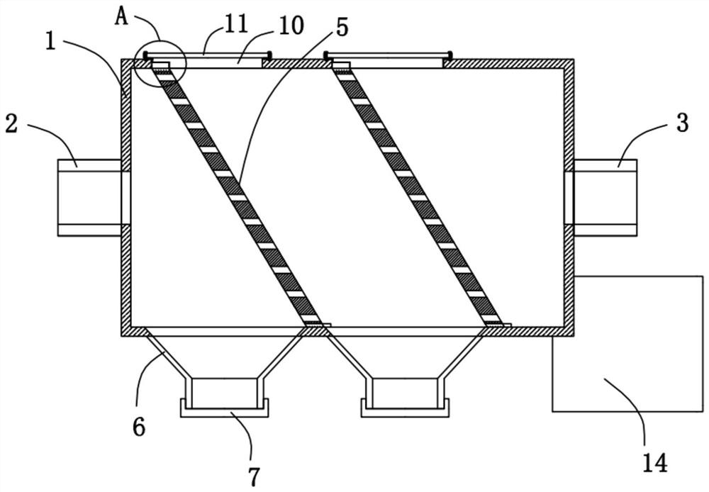
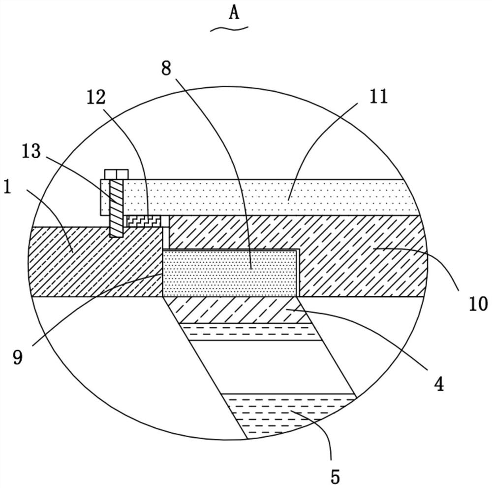
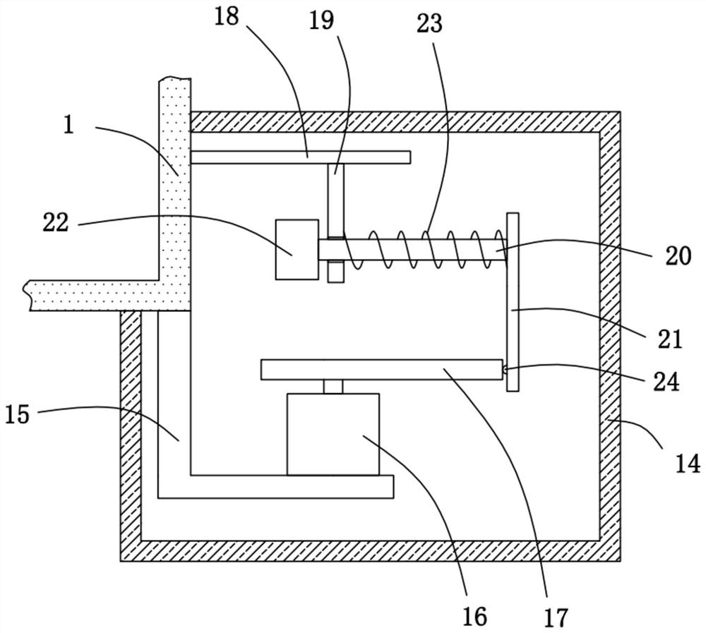
[0004] In order to overcome the problems existing in the prior art that exhaust gas pollutes the environment and damages human health, the present invention provides an exhaust dust removal device for construction machinery, which includes a box, and the two sides of the box are respectively provided with an inlet pipe and an outlet pipe , the box is provided with two support frames, the support frame is inclined, and the filter screen is fixedly installed in the support frame, and a dust collection bucket is provided under the filter screen, and the dust collection bucket The bottom is screwed with a cover, the top of the support frame is fixed with a connection block, and the top of the box is provided with two installation holes, and a compression block is arranged in the installation hole, and the compression block is in contact with the connection block , the top of the pressing block is provided with a cover plate, and the cover plate is fixedly connected with the box body, and a protective cover fixedly connected with the box body is provided under the outlet pipe, and a protective cover is installed in the protective cover With vibration mechanism

Method used


Image

  • Tail gas dust removal device for engineering machinery
  • Tail gas dust removal device for engineering machinery
  • Tail gas dust removal device for engineering machinery

Examples


Embodiment Construction

[0021] The present invention will be described in further detail below in conjunction with the accompanying drawings and embodiments. It should be understood that the specific embodiments described here are only used to explain the present invention, not to limit the present invention.

[0022] Please refer to Figure 1-5 , the present invention provides a technical solution: a kind of tail gas dedusting device for construction machinery, comprising a box body 1, the two sides of the box body 1 are respectively provided with an air inlet pipe 2 and an air outlet pipe 3, and the box body 1 is provided with Two support frames 4, the support frame 4 is inclined to set, the filter screen 5 is fixedly installed in the support frame 4, the bottom of the filter screen 5 is provided with a dust collection bucket 6, and the bottom of the dust collection bucket 6 A cover 7 is threadedly installed, a connecting block 8 is fixedly installed on the top of the support frame 4, and two moun...


PUM


Abstract

The invention provides a tail gas dust removal device for engineering machinery. The device comprises a box body, a gas inlet pipe and a gas outlet pipe are respectively arranged on the two sides of the box body, two supporting frames are obliquely arranged in the box body, filter screens are fixedly arranged in the supporting frames, dust collecting hoppers are arranged below the filter screens, covers are installed at the bottoms of the dust collecting hoppers in a threaded mode, and connecting blocks are fixedly installed at the tops of the supporting frames. Two mounting holes are formed in the top of the box body, pressing blocks are arranged in the mounting holes and make contact with the connecting blocks, cover plates are arranged at the tops of the pressing blocks, and the cover plates are fixedly connected with the box body. A protective cover fixedly connected with the box body is arranged below the gas outlet pipe, and a vibration mechanism is installed in the protective cover. The tail gas dust removal device is convenient to use, tail gas of engineering machinery can be filtered, particles in the tail gas can be treated in a centralized mode, and meanwhile the filter screens can be replaced quickly.

Description

technical field [0001] The invention relates to the technical field of construction machinery, in particular to an exhaust dust removal device for construction machinery. Background technique [0002] Construction machinery is an important part of the equipment industry. In a nutshell, all the mechanical equipment necessary for comprehensive mechanized construction projects required for earthwork construction projects, road surface construction and maintenance, mobile lifting and loading and unloading operations, and various construction projects are called construction machinery. [0003] During the use of construction machinery, a lot of exhaust gas is often discharged, which not only causes environmental pollution, but also seriously affects people's health. Therefore, an exhaust dust removal device for construction machinery is proposed. Contents of the invention [0004] In order to overcome the problems existing in the prior art that exhaust gas pollutes the environ...

Claims


Application Information

Patent Timeline
IPC IPC(8): B01D46/12B01D46/00
CPCB01D46/12B01D46/0005B01D46/0002B01D46/62B01D46/76
Inventor 金传辉金菘乔翔宇陈坚
Owner 扬州华交轨道交通科技有限公司
Learn More