
High-speed cutting device for rolling parts

A cutting device, high-speed technology, applied in shearing devices, accessories of shearing machines, metal processing machinery parts, etc., can solve the problems of inability to achieve high-speed cutting, low production efficiency, and low rolling speed.

Pending Publication Date: 2021-04-23
博瑞孚曼机械科技(苏州)有限公司
View PDF0 Cites 0 Cited by
  • Summary
  • Abstract
  • Description
  • Claims
  • Application Information

AI Technical Summary

Problems solved by technology

[0003] The existing rolling parts cutting device has large burrs after rolling cutting, and the rolling speed is low, which also leads to low production efficiency, and cannot realize high-speed cutting in the online state

Method used


Image

  • High-speed cutting device for rolling parts
  • High-speed cutting device for rolling parts
  • High-speed cutting device for rolling parts

Examples


Embodiment

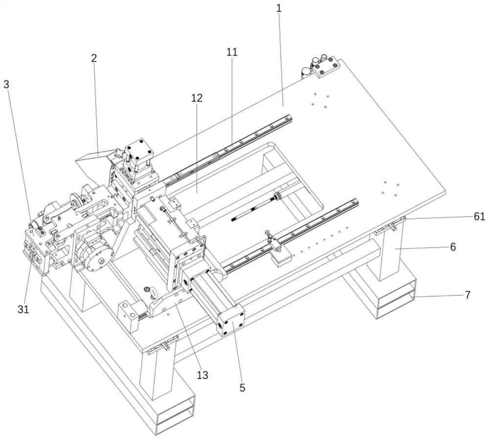
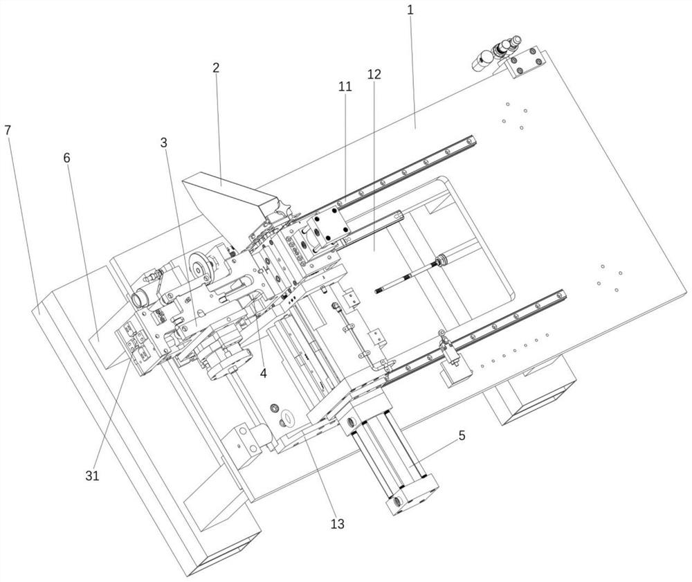
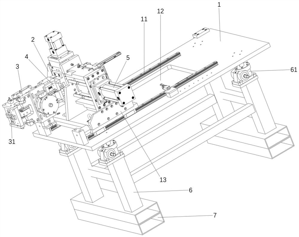
[0035] Such as Figure 1-6 As shown, the present invention provides a high-speed cutting device for rolled parts, including a pedestal 1, an unloading system 2, a feeding system 3, a compacting system 4 and a cutting system 5, wherein the pedestal 1 is provided with an opening that penetrates the pedestal 1 slot 12;

[0036] Both sides of the slot 12 are provided with slide rails 11, wherein a slide base 13 is installed on the slide rail 11, and the slide base 13 can slide along the slide rail 11 for convenient operation;

[0037] A pressing system 4 and a feeding system 3 are installed on the sliding base 13, wherein the pressing system 4 is fixed to the feeding system 3;

[0038] The pressing system 4 comprises a first clamping piece 41 and a second clamping piece 42, wherein a clamping hole 43 is formed between the ends of the first clamping piece 41 and the second clamping piece 42, and the clamping hole 43 The workpiece can be clamped, and when the cutting system 5 is c...


PUM


Abstract

The invention discloses a high-speed cutting device for rolling parts. The high-speed cutting device comprises a pedestal, a discharging system, a feeding system, a pressing system and a cutting system, wherein an open groove penetrating through the pedestal is formed in the pedestal; sliding rails are arranged on the two sides of the open groove; a sliding base is mounted on the sliding rails; the pressing system and the feeding system are mounted on the sliding base and fixed; the pressing system comprises a first clamping piece and a second clamping piece; a clamping hole is formed between the end of the first clamping piece and the end of the second clamping piece; a feeding port is formed in the end of the feeding system and communicates with the clamping hole; the cutting system is arranged on one side of the pressing system; and the discharging system is mounted at the end of the cutting system. By adoption of the high-speed cutting device for the rolling parts, the problem that burrs exist after the rolling parts are cut off is solved, high-speed cutting can be achieved, and the production efficiency is improved; and high-speed cutting in the online state is achieved.

Description

technical field [0001] The invention relates to a cutting device for rolling parts, in particular to a high-speed cutting device for rolling parts. Background technique [0002] With the continuous tightening of national environmental protection regulations and fuel economy policies, energy saving and emission reduction have become an important trend in the current automobile development. At the same time, with the development of the automobile industry, fuel economy, low carbon emissions and higher safety have put forward new requirements and challenges for the lightweight of the automobile body. In the auto parts, there are more and more roll forming products. Roll forming materials have the characteristics of high material utilization rate and high forming efficiency. [0003] The existing rolling part cutting device has large burrs after rolling cutting, and the rolling speed is low, which also leads to low production efficiency, and cannot realize high-speed cutting in...

Claims


Application Information

Patent Timeline
IPC IPC(8): B23D33/02B23Q1/01B23Q7/00
CPCB23D33/02B23Q1/01B23Q7/00
Inventor 李艳冰池金波
Owner 博瑞孚曼机械科技(苏州)有限公司
Learn More