Steering device of railway locomotive

A technology for railway locomotives and steering devices, which is applied in the directions of railway car body parts, bogies, devices for lateral relative movement between the underframe and the bogies, etc. tilt, etc.

Pending Publication Date: 2021-04-23
ZHENGZHOU RAILWAY VOCATIONAL & TECH COLLEGE
View PDF4 Cites 0 Cited by
  • Summary
  • Abstract
  • Description
  • Claims
  • Application Information

AI Technical Summary

Problems solved by technology

The traditional bogie has a simple structure. Although it has a large buffering effect on the running of the locomotive, in the actual steering operation, due to the height difference between the two wheel sets at the turn, the carriage will not move in a short time when turning. If the car is tilted sharply, the car cannot automatically adjust the tilt angle, resulting in poor comfort in the car

Method used


Image

  • Steering device of railway locomotive
  • Steering device of railway locomotive
  • Steering device of railway locomotive

Examples


Embodiment 1

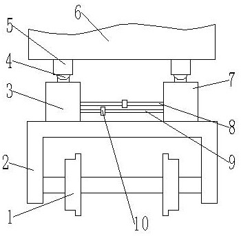
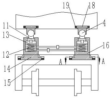
[0036] Such as Figure 1-5 As shown, a steering device of a railway locomotive comprises a main body 2 of a railway locomotive bogie and wheelsets 1 arranged on both sides of the main body 2; both sides of the upper end of the main body 2 are provided with traction devices, and the traction devices are used for The traction compartment 6 moves, and the traction device includes a first traction device 3 and a second traction device 7; symmetrically arranged between the first traction device 3 and the second traction device 7; the other end of the traction device is connected to the carriage 6 connection; a first pipeline 8 and a second pipeline 9 are arranged between the traction devices, and a check valve 10 is arranged on the first pipeline 8 and the second pipeline 9, and the two one-way valves The flow direction of the liquid medium in the valve 10 is opposite; one end of the first pipeline 8 and one end of the second pipeline 9 communicate with the first traction device 3,...

Embodiment 2

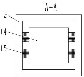
[0045] The difference from Embodiment 1 is that in order to improve the comfort of the cabin when turning, the diameter R1 of the spring, the wire diameter r of the spring, the effective number of coils N of the spring and the diameter R2 of the cavity satisfy the following relationship: R1·R2=α·(N·r) 2 ; Among them, the units of R1, R2, and r are cm; α is the correlation coefficient, and the value range is 3-10. When α is less than 3, the spring stiffness is large and the shock absorption performance is poor, which affects the fluidity of the liquid medium. When α is greater than 10, the spring stiffness is small. The flow between the second traction device 7 and the second traction device 7 is rapid, and the inclination rate of the compartment 6 is relatively large, causing the comfort of the compartment 6 to be poor.

Embodiment 3

[0047] In conjunction with embodiment two, the simulation experiment is carried out to the turning of the locomotive, and the steering angle of the simulated railway curve is 120 degrees, and the angle of the cross section at the turning is 30 degrees, that is, when turning, the angle between the plane where the wheelset 1 is located and the horizontal plane is 30 degrees, in order to simplify the experiment, in the locomotive model, the second spring is freely suspended, the lower end of the spring is connected to the steel ball, the weight of the steel ball is 50N, and the upper end of the second spring is connected to the tension sensor. The locomotive drives through the curve at a constant speed, and the speed is taken as 10m / s, experiment with α as 1, 3, 6, 10, and 12 respectively, and observe the value of the tension sensor. The greater the tension, the worse the stability and comfort of the car when turning; the experimental results are as follows, When α is 1, the pulli...


PUM


Abstract

The invention discloses a steering device of a railway locomotive. The steering device comprises a main body of a railway locomotive bogie and wheel sets arranged on the two sides of the main body. Traction devices are arranged on two sides of the upper end of the main body, and comprise a first traction device and a second traction device; the first traction device and the second traction device are symmetrically arranged; the other ends of the traction devices are connected with the carriage; a first pipeline and a second pipeline are arranged between the traction devices; one-way valves are arranged on the first pipeline and the second pipeline; one end of the first pipeline and one end of the second pipeline are communicated with the first traction device, and the other end of the first pipeline and the other end of the second pipeline are communicated with the second traction device. By arranging the first traction device and the second traction device, when the locomotive steers, the inclination angle of the carriage can be automatically adjusted, and when the carriage inclines, the first traction device and the second traction device play a role in buffering, so that the comfort of the carriage during steering is improved.

Description

technical field [0001] The invention belongs to the technical field of railway locomotive equipment, and in particular relates to a steering device of a railway locomotive. Background technique [0002] The structure of the railway locomotive bogie makes the locomotive have good steering characteristics to ease the interaction between the vehicle and the line. The use of the bogie reduces the impact between the locomotive and the line and improves the stability and safety of the locomotive operation. . The traditional bogie has a simple structure. Although it has a large buffering effect on the running of the locomotive, in the actual steering operation, due to the height difference between the two wheel sets at the turn, the carriage will not move in a short time when turning. If it is tilted sharply, the cabin cannot automatically adjust the tilt angle, resulting in poor comfort in the cabin. Contents of the invention [0003] In view of the deficiencies in the prior a...

Claims


Application Information

Patent Timeline
Patent Type & Authority Applications(China)
IPC IPC(8): B61F5/06B61F5/12B61F5/24
CPCB61F5/06B61F5/127B61F5/245
Inventor 曲素荣高伟张瑞坤张琼洁毕红雪张金瑞陈然
Owner ZHENGZHOU RAILWAY VOCATIONAL & TECH COLLEGE
Why Eureka
Try Eureka