Hydrodynamic force-based water conservancy riverway floating garbage collection device
A technology of garbage collection and hydrodynamics, which is applied in water conservancy projects, hydropower generation, and open-air water surface cleaning.
- Summary
- Abstract
- Description
- Claims
- Application Information
AI Technical Summary
Problems solved by technology
Method used
Image


Examples
Embodiment 2
[0040] When used, such as figure 2 As shown, the floating mechanism has a first buoyancy frame 401, an air bag 402, a connecting frame 403, a second buoyancy frame 404, a third buoyancy frame 405, a first fixed frame 406 and a second fixed frame 407, on the right side of the rail network 1 The first buoyancy frame 401 is provided, the left side of the first buoyancy frame 401 is provided with a gap and the right side is provided with a groove, and the lower part of the first buoyancy frame 401 is fixedly connected with four airbags 402 evenly distributed, on the first buoyancy frame 401 A connection frame 403 is fixedly connected with the second buoyancy frame 404, the second buoyancy frame 404 is arranged on the left side of the guide rail net 1, the connection frame 403 straddles the top of the guide rail net 1, and the third buoyancy frame 405 is fixedly connected to the first buoyancy frame. On the right side of the frame 401 with grooves, the first fixed frame 406 is fix...
Embodiment 3
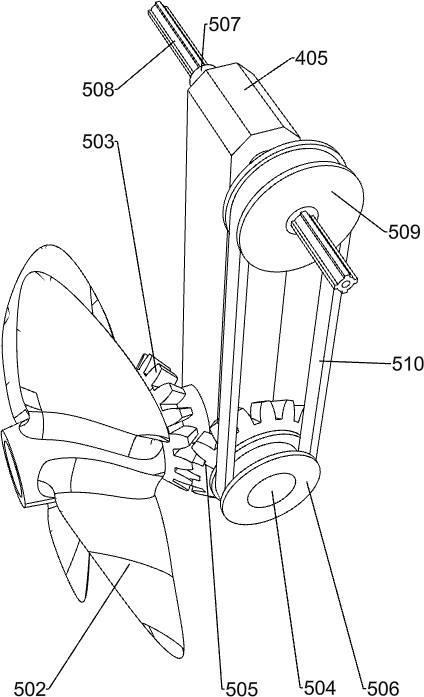
[0043] When used, such as Figure 3-4 As shown, the power mechanism has a first rotating shaft 501, a spiral fan blade 502, a first bevel gear 503, a second rotating shaft 504, a second bevel gear 505, a first synchronous wheel 506, a third rotating shaft 507, a cross guide rail 508, a second The synchronous wheel 509 and the first belt 510, the first rotating shaft 501 is rotatably connected to the lower left side of the third buoyancy frame 405, the spiral fan blade 502 is fixedly connected to the left end of the first rotating shaft 501, and the first bevel gear 503 is fixedly connected to the first rotating shaft 501 On the right end close to the spiral fan blade 502, the second rotating shaft 504 is rotatably connected to the lower front side of the third buoyancy frame 405, the second bevel gear 505 is fixedly connected to the front end of the second rotating shaft 504, the first bevel gear 503 and the second bevel gear 505 meshes, the first synchronous wheel 506 is fixe...
Embodiment 4
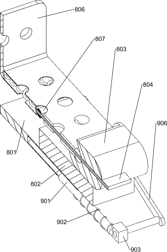
[0046] When used, such as Figure 5-6 As shown, the gear assembly has a third bevel gear 601, a fourth bevel gear 602, a fourth rotating shaft 603, a fifth bevel gear 604, a fifth rotating shaft 605, a small synchronous wheel 6051, a second belt 606, a first gear 607, a block 608, the first fixed piece 6081, the second fixed piece 6082, the sixth rotating shaft 609, the second gear 610, the first guide wheel 611 and the second guide wheel 612, the third bevel gear 601, the fourth bevel gear 602, the fourth The rotating shaft 603, the fifth bevel gear 604, the fifth rotating shaft 605 and the small synchronous wheel 6051 are all installed in the right side of the groove on the first buoyancy frame 401, and the third bevel gear 601 and the fourth bevel gear 602 are fixedly connected on the bearing Both sides of the cover are slidingly connected with the cross guide rail 508, the fourth rotating shaft 603 is rotationally connected to the lower part of the first fixed frame 406, t...
PUM
 Abstract
Description
Claims
Application Information
 - R&D Engineer
- R&D Manager
- IP Professional
- Industry Leading Data Capabilities
- Powerful AI technology
- Patent DNA Extraction
Browse by: Latest US Patents, China's latest patents, Technical Efficacy Thesaurus, Application Domain, Technology Topic.
© 2024 PatSnap. All rights reserved.Legal|Privacy policy|Modern Slavery Act Transparency Statement|Sitemap