Eureka AIR delivers breakthrough ideas for toughest innovation challenges, trusted by R&D personnel around the world.

Convenient-to-disassemble-and-assemble rotor seat of refrigeration compressor

A refrigeration compressor, a technology that facilitates disassembly and assembly, is applied in the field of compressors, and can solve the problems of difficult rotor positioning, complicated installation, and unstable operation.

Active Publication Date: 2021-04-23
江苏合球机械科技有限公司
View PDF5 Cites 0 Cited by
  • Summary
  • Abstract
  • Description
  • Claims
  • Application Information

AI Technical Summary

Problems solved by technology

For refrigeration compressors, electric motors are essential. Electric motors can convert electrical energy into mechanical energy. According to their rotor and stator installation methods, they can be divided into outer rotor motors and inner rotor motors. The existing rotor seats of refrigeration compressors have poor connectivity. , it is not easy to disassemble and maintain, and the installation is more complicated, time-consuming and labor-intensive. Secondly, the rotor is fixed in the rotor seat and rotates with the shaft, which will make the positioning of the rotor difficult, unstable, and easy to cause damage to the motor rotor coil, thus affecting The normal operation of the motor rotor leads to low work efficiency. Finally, when the internal rotor rotates at high speed, it will cause the rotor seat to shake, making the operation unstable, without shock absorption, and reducing the service life. Therefore, we propose a Rotor seat for easy disassembly and assembly of refrigeration compressors

Method used


Image

  • Convenient-to-disassemble-and-assemble rotor seat of refrigeration compressor
  • Convenient-to-disassemble-and-assemble rotor seat of refrigeration compressor
  • Convenient-to-disassemble-and-assemble rotor seat of refrigeration compressor

Examples


Embodiment Construction

[0027] The following will clearly and completely describe the technical solutions in the embodiments of the present invention with reference to the accompanying drawings in the embodiments of the present invention. Obviously, the described embodiments are only some, not all, embodiments of the present invention. Based on the embodiments of the present invention, all other embodiments obtained by persons of ordinary skill in the art without making creative efforts belong to the protection scope of the present invention.

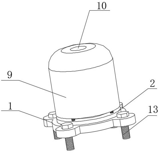
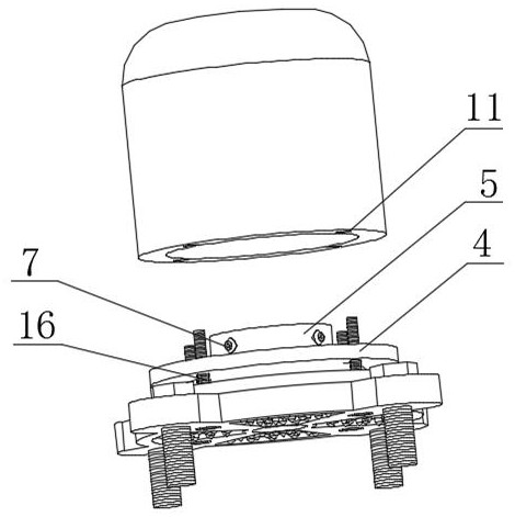
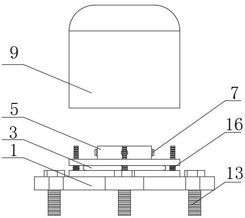
[0028] see Figure 1-6 , a rotor seat for convenient disassembly and assembly of refrigeration compressors, comprising a base 1, a fixed plate 2 is arranged on the outer surface of the upper end of the base 1, a shock absorbing pad 3 is arranged on the outer surface of the upper end of the fixed plate 2, and the shock absorbing pad 3 The outer surface of the upper end is provided with a mounting ring 4, the outer surface of the upper end of the mounting ring 4...


PUM


Abstract

The invention relates to the technical field of compressors, and discloses a convenient-to-disassemble-and-assemble rotor seat for a refrigeration compressor, which comprises a base, a fixed disc is arranged on the outer surface of the upper end of the base, a shock pad is arranged on the outer surface of the upper end of the fixed disc, and a mounting ring is arranged on the outer surface of the upper end of the shock pad; and a connecting ring is arranged on the outer surface of the upper end of the mounting ring, an inner connecting ring is arranged on the outer surface of the inner side end of the connecting ring, a limiting ring is arranged on the outer surface of the side end of the inner connecting ring, and locking pins are arranged on the outer surface of the side end of the connecting ring. The convenient-to-disassemble-and-assemble rotor seat for the refrigeration compressor is simple in structure, high in connectivity and convenient to operate, has the advantages of being convenient to assemble and disassemble, facilitating internal maintenance, enhancing connectivity, having a limiting effect on a rotating shaft, preventing internal deviation from influencing the using effect and having a damping function, therefore, the service life of a rotor is prolonged, the using stability is improved, and the use effect is improved.

Description

technical field [0001] The invention relates to the technical field of compressors, in particular to a rotor seat for convenient assembly and disassembly of refrigeration compressors. Background technique [0002] The refrigeration compressor is the core energy-consuming component of the refrigeration system. The excellence of the refrigeration system is reflected by the capacity of the compressor. The most direct and effective means to improve the efficiency of the refrigeration system is to improve the efficiency of the compressor. Refrigeration compressors are widely used, such as refrigerators, freezers, fresh-keeping, air conditioners, etc. For refrigeration compressors, electric motors are essential. Electric motors can convert electrical energy into mechanical energy. According to their rotor and stator installation methods, they can be divided into outer rotor motors and inner rotor motors. The existing rotor seats of refrigeration compressors have poor connectivity....

Claims


Application Information

Patent Timeline
IPC IPC(8): F04B35/04F04B39/00
CPCF04B35/04F04B39/0044
Inventor 黎思忠李建国李熙刘清
Owner 江苏合球机械科技有限公司
Why Eureka
Eureka Blog
Learn More