Leveling supporting leg

A leveling and nut technology, applied in the direction of controlling mechanical energy, electrical components, electromechanical devices, etc., can solve the problems of reducing the impact force of the leveling legs, and the locking of the rear legs, so as to reduce the starting torque and avoid the screw lock. Dead, low-cost effects

Inactive Publication Date: 2021-04-23
WUHAN BINHU ELECTRONICS
View PDF13 Cites 2 Cited by
  • Summary
  • Abstract
  • Description
  • Claims
  • Application Information

AI Technical Summary

Problems solved by technology

The invention reduces the recovery impact force of the leveling support leg through the butterfly spring installed at the end of the trapezoidal spiral pair, and solves the problem that the support leg is locked after long-term storage

Method used


Image

  • Leveling supporting leg
  • Leveling supporting leg
  • Leveling supporting leg

Examples


Embodiment Construction

[0019] The technical solution of the present invention will be further described below in conjunction with the accompanying drawings.

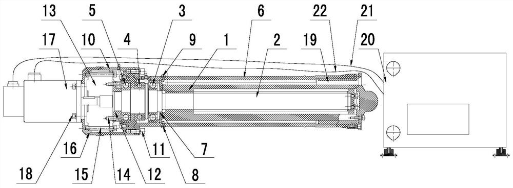
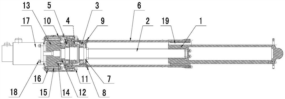
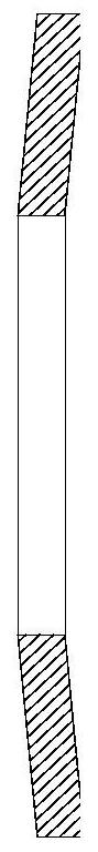
[0020] like Figure 1 to Figure 4 As shown, a leveling support leg of the present invention includes a strut nut 1, a housing 6, a butterfly spring 7, a screw rod 2, a fixing screw, and a key 19, wherein the strut nut 1 is installed on the outside of the screw rod 2, and the housing Body 6 afterbody and strut nut 1 are provided with groove, and key 19 is installed in the groove, and key 19 can prevent strut nut 1 from rotating, and strut nut 1 can only reciprocate axially. The butterfly spring 7 is fixedly installed on the housing 6 by fixing screws, so that the strut nut 1 slides backward and gradually squeezes the butterfly spring 7 when the stroke end of the leg is leveled. The butterfly spring 7 is subjected to axial load Compression deformation occurs, and as the amount of compression deformation increases, the axial load it bears is gre...


PUM


Abstract

The invention relates to the field of automatic lifting equipment, and particularly relates to a leveling supporting leg. A belleville spring is fixedly installed on a shell through a fixing screw, a sliding column nut slides backwards and gradually extrudes the belleville spring at the tail end of the stroke of the leveling supporting leg, the belleville spring is compressed and deformed due to the axial load, and the axial load borne by the belleville spring is larger along with the increase of the compression deformation amount. The recovery impact force of the leveling supporting leg is reduced, and the problem that the supporting leg is locked after being placed for a long time is solved.

Description

technical field [0001] The invention relates to the field of automatic lifting equipment, in particular to a butterfly spring and a leveling leg device for preventing locking. Background technique [0002] The existing leveling system is used more and more frequently. During the working process of the leveling leg, it needs to be stretched out first and then recovered. Only when the leveling leg is fully recovered can the extension length of the leveling leg be effectively controlled when it is stretched out next time. [0003] When recycling the existing leveling legs, photoelectric sensors or contact switches are often used. When the signal is detected, it is considered that the recovery is in place. This will increase the electrical equipment, which will lead to a decrease in system reliability, and generally the built-in photoelectric sensor or contact switch is more expensive. , especially in high and low temperature working environments, four leveling legs will increas...

Claims


Application Information

Patent Timeline
Patent Type & Authority Applications(China)
IPC IPC(8): F16H25/24H02K7/06H02K7/10
CPCF16H25/24H02K7/06H02K7/10
Inventor 何汉忠王进军王德宇沈小川文思钊
Owner WUHAN BINHU ELECTRONICS
Why Eureka
Try Eureka