Rock structural surface cyclic shearing device and test method of opposite-vertex clamping structure

A technology of clamping structure and shearing device, which is applied in the direction of testing material strength by applying stable shear force, measuring device, and testing material strength by applying repetitive force/pulsation force, which can solve the problem of affecting test accuracy, shaking, etc. problem, to improve test accuracy and avoid shaking

Active Publication Date: 2021-04-23
INST OF ROCK AND SOIL MECHANICS - CHINESE ACAD OF SCI
View PDF10 Cites 3 Cited by
  • Summary
  • Abstract
  • Description
  • Claims
  • Application Information

AI Technical Summary

Problems solved by technology

[0004] However, in practice, the structural surface sample cannot be closely matched with the shear box because of the manufacturing tolerance, so there is a lot of shaking during the shearing process. In order to avoid this problem, in some designs, the shear box A special design is adopted so that when the test piece is installed, the shear box can clamp the test piece, a typical example is (Zheng Bowen et al., a shear box for testing the cyclic shear characteristics of rock mass structural surfaces, application publication number CN 110411822A)
[0005] This design solves the problem of sloshing of the structural surface sample in the shear box due to manufacturing tolerances at the beginning of the test, but during the cyclic shearing process, the sample is compressed by the lateral shear force from the shear box , will inevitably produce lateral deformation, so that even if the sample is fastened before the test, after many cycles, the sample is still due to the lateral deformation (shortened by the side) Shake in the box, which affects the test accuracy

Method used


Image

  • Rock structural surface cyclic shearing device and test method of opposite-vertex clamping structure
  • Rock structural surface cyclic shearing device and test method of opposite-vertex clamping structure
  • Rock structural surface cyclic shearing device and test method of opposite-vertex clamping structure

Examples


Embodiment 1

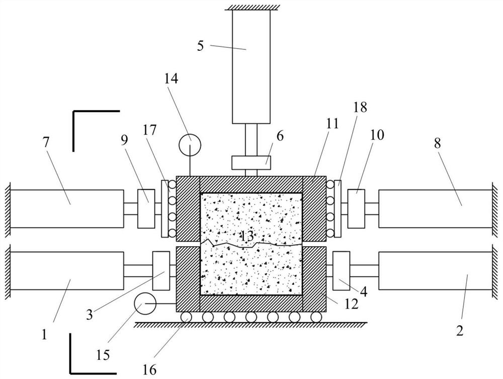
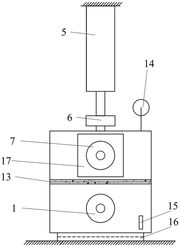
[0034] A cyclic shearing device for a rock structural surface with a top clamping structure, including an upper shear box 11 and a lower shear box 12, and an upper positive shear loading jack 7 symmetrically arranged on both sides of the upper shear box 11 And the upper negative shear loading jack 8, also includes the lower positive shear loading jack 1 and the lower negative shear loading jack 2 symmetrically arranged on both sides of the lower shear box 12,

[0035] The telescoping end of the upper positive shear loading jack 7 is provided with an upper forward shear force sensor 9 and is connected to the connecting portion of the first upper roller support 17, and the roller portion of the first upper roller support 17 is connected to the upper shear load. One side of the box 11 is offset; the telescopic end of the upper negative shear load jack 8 is provided with an upper negative shear force sensor 10 and is connected with the connecting portion of the second upper roller ...

Embodiment 2

[0048] A method for cyclic shearing test of a rock structural surface with a clamping structure against the top, utilizing the cyclic shearing device for a structural surface of rock with a clamping structure against the top described in Example 1, comprising the following steps:

[0049] Step 1. Assemble the cyclic shearing device for the rock structural surface of the top-to-top clamping structure;

[0050] Step 2, ensure that the telescopic ends of the lower positive shear loading jack 1, the lower negative shear loading jack 2, the upper positive shear loading jack 7, and the upper negative shear loading jack 8 are retracted;

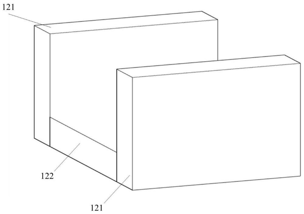
[0051] Step 3, install the rock mass structural surface sample 13 between the upper shear box 11 and the lower shear box 12, and set the upper shear box 11, the rock mass structural surface sample 13 and the lower shear box 12 in a horizontal On the roller support 16;

[0052] Step 4, manually aligning the upper shear box 11 and the lower shear box...

Embodiment 3

[0059] A method for cyclic shearing test of a rock structural surface with a clamping structure against the top, utilizing the cyclic shearing device for a structural surface of rock with a clamping structure against the top described in Example 1, comprising the following steps:

[0060] Step 1. Assemble the cyclic shearing device for the rock structural surface of the top-to-top clamping structure;

[0061] Step 2, ensure that the telescopic ends of the lower positive shear loading jack 1, the lower negative shear loading jack 2, the upper positive shear loading jack 7, and the upper negative shear loading jack 8 are retracted;

[0062] Step 3, install the rock mass structural surface sample 13 between the upper shear box 11 and the lower shear box 12, and set the upper shear box 11, the rock mass structural surface sample 13 and the lower shear box 12 in a horizontal On the roller support 16;

[0063] Step 4, manually aligning the upper shear box 11 and the lower shear box...


PUM


Abstract

The invention discloses a rock structural surface cyclic shearing device of an opposite-vertex clamping structure, wherein the device comprises an upper shearing box and a lower shearing box, and further comprises an upper positive shearing loading jack and an upper negative shearing loading jack which are symmetrically arranged on two sides of the upper shearing box; the device also comprises a lower positive shearing loading jack and a lower negative shearing loading jack which are symmetrically arranged on the two sides of the lower shearing box, and a normal force sensor is arranged at the telescopic end of the normal loading servo jack and abuts against the top of the upper shearing box. The invention further discloses a rock structural surface cyclic shear test method of the opposite-vertex clamping structure; the test sample can be kept in a fastened state from the beginning to the end in a cyclic experiment, a shear test piece is prevented from shaking in the shear box in cyclic shear, and the test precision is improved.

Description

technical field [0001] The invention belongs to the technical fields of civil engineering, water conservancy and hydropower engineering, and new energy engineering, and specifically relates to a cyclic shearing device for a rock structural surface with a top clamping structure, and also relates to a cyclic shearing device for a rock structural surface with a top clamping structure experiment method. Background technique [0002] The shear characteristics of rock mass structural planes are very important for the stability evaluation of geotechnical engineering such as slope engineering and tunnel engineering. Key indicators for disease prediction and control. Shearing in the tangential direction of the structural plane, that is, direct shearing (direct shear) is the most commonly used test method for determining the structural plane of rock mass, and has been widely used. Furthermore, there are quite a lot of working conditions that need to measure the shear mechanical prop...

Claims


Application Information

Patent Timeline
Patent Type & Authority Applications(China)
IPC IPC(8): G01N3/04G01N3/24G01N3/36
CPCG01N3/04G01N3/24G01N3/36G01N2203/0003G01N2203/0005G01N2203/0042G01N2203/0025
Inventor 崔臻盛谦张茂础梅贤丞
Owner INST OF ROCK AND SOIL MECHANICS - CHINESE ACAD OF SCI
Why Eureka
Try Eureka