

Pressure relief device and housing comprising same
A technology of pressure relief device and housing, which is applied in substation/power distribution device housing, electrical equipment housing/cabinet/drawer, electrical components, etc. It can solve the problems of diaphragm removal, damage, diaphragm tearing, etc.
- Summary
- Abstract
- Description
- Claims
- Application Information
AI Technical Summary
Problems solved by technology
Method used
Image

Examples
Embodiment Construction
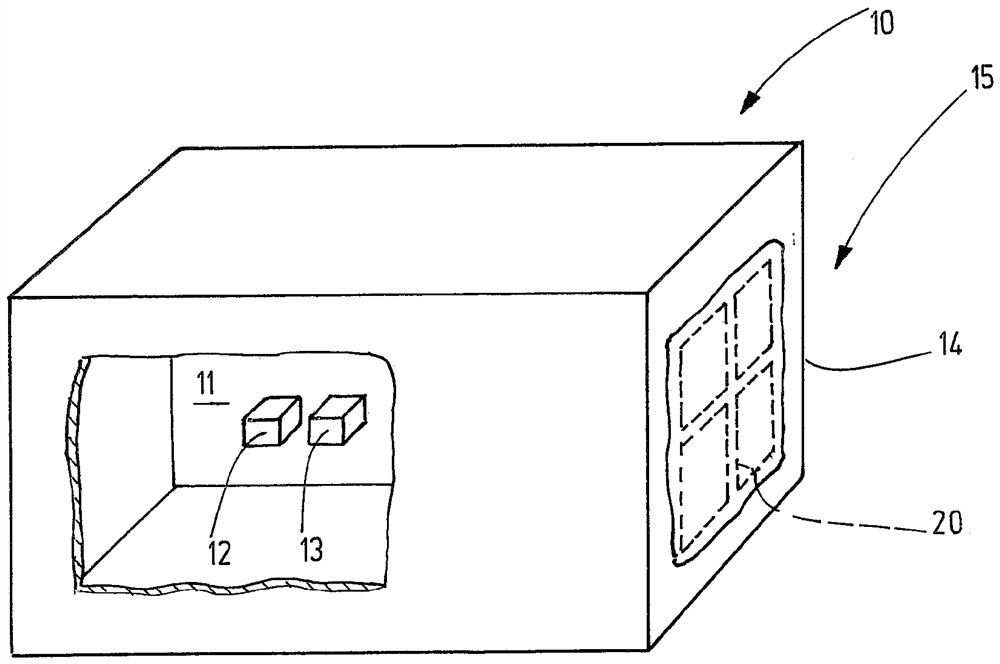
[0028] exist figure 1 3D shows a housing 10 in partially cutaway form, which encloses an interior space 11, in which the symbolically shown components 12, 13 can be installed there, said components being in operation, for example due to Heat generation, spark formation, radiation or other influences may act as a source of ignition. The housing 10 separates these ignition sources 12 , 13 from the surroundings 14 in order to prevent a flame or explosion occurring in the interior 11 from propagating into the surroundings 14 . The housing 10 is preferably a housing of the “pressure-resistant encapsulation” type of protection (ex-d). However, in order to achieve a rapid pressure equalization and therefore a rapid reduction of the excess pressure generated in the housing 10, especially in the event of an explosion in the interior 11, a pressure relief device 15 is provided, which in the figure 1 Neutrons are exemplarily shown mounted at the sides of the housing 10 . However, the ...
PUM
 Abstract
Description
Claims
Application Information