An engine thermal management system and method

A heat management system and engine technology, applied to engine components, combustion engines, machines/engines, etc., can solve problems such as overcooling and partial cooling, and achieve the effects of reducing working pressure, saving energy, and ensuring normal operation

Active Publication Date: 2022-07-08
NINGBO GEELY ROYAL ENGINE COMPONENTS +1
View PDF11 Cites 0 Cited by
  • Summary
  • Abstract
  • Description
  • Claims
  • Application Information

AI Technical Summary

Problems solved by technology

Therefore, if the serial cooling method is adopted for the cylinder block and the cylinder head, local overcooling or insufficient local cooling may easily occur

Method used


Image

  • An engine thermal management system and method
  • An engine thermal management system and method

Examples


Embodiment 1

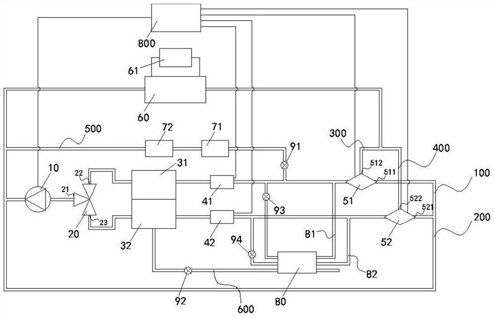
[0040] please combine figure 1 , this embodiment provides an engine thermal management system, including a coolant pump 10, a three-way valve 20, a cylinder head cooling jacket 31, a cylinder block cooling jacket 32, a first temperature sensor 41, a second temperature sensor 42, a first section The thermostat 51, the second thermostat 52, the radiator 60 and the control unit 800; the first temperature sensor 41 can detect the temperature of the coolant passing through the cylinder head cooling jacket 31, and the second temperature sensor 42 can detecting the temperature of the coolant passing through the cylinder cooling jacket 32;

[0041] The three-way valve 20 includes a three-way valve inlet 21, a three-way valve first outlet 22, and a three-way valve second outlet 23. The three-way valve inlet 21 is connected to the liquid outlet end of the coolant pump 10, so The first outlet 22 of the three-way valve is connected to the cylinder head cooling jacket 31, the cylinder hea...

Embodiment 2

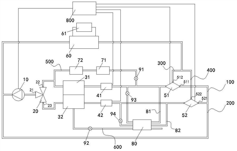
[0060] please combine figure 2 , This embodiment is an engine thermal management system. The difference from Embodiment 1 is that the intercooler 72 is connected to the liquid inlet end of the cylinder head cooling jacket 31. The cylinder head cooling jacket 31, the first The temperature sensor 41 , the temperature regulator 71 and the intercooler 72 constitute the engine intake heat management branch 500 .

[0061] Of course, the intercooler 72 may be connected at other positions besides the above-mentioned connection positions, and only needs to play the role of leading out the cooling liquid in the engine intake heat management branch 500 .

[0062] The working principle and beneficial effects of an engine passenger management system provided in this embodiment are the same as those in Embodiment 1, which will not be repeated here.

Embodiment 3

[0064] This embodiment provides an engine thermal management method, which is used in any one of the engine thermal management systems provided in the above embodiments, including:

[0065] a first temperature sensor collects a first temperature, where the first temperature is the temperature of the cooling liquid after passing through the cylinder head cooling jacket, and sends the first temperature to the control unit;

[0066] The control unit compares the first temperature with a preset first temperature threshold, and when the first temperature is less than or equal to the first temperature threshold, the control unit controls the first thermostatic valve The first connection port is turned on, and the first cylinder head heat dissipation circuit is used to thermally manage the engine cylinder head. When the first temperature is greater than the first temperature threshold, the control unit controls the first throttle temperature The valve conducts the second connection p...


PUM


Abstract

The invention provides an engine thermal management system, comprising a first cylinder head heat dissipation circuit composed of a coolant pump, a three-way valve, a cylinder head cooling jacket, a first temperature sensor and a first thermostat, a coolant pump, a three-way The valve, the cylinder block cooling jacket, the second temperature sensor and the second thermostat constitute the first cylinder block heat dissipation circuit, the coolant pump, the three-way valve, the cylinder head cooling jacket, the first temperature sensor, the first thermostat and the heat dissipation The second cylinder head heat dissipation circuit and the coolant pump, the three-way valve, the second temperature sensor, the second thermostat and the radiator form the second cylinder block heat dissipation circuit; on this basis, the present invention also provides an engine Thermal management method: It can carry out targeted thermal management according to the actual thermal load of the cylinder block and cylinder head, avoiding the local excessive cooling or insufficient cooling that is easily caused by traditional thermal management methods, and ensuring that all parts of the engine are at a suitable temperature. It is beneficial to improve the working efficiency and service life of the engine.

Description

technical field [0001] The invention relates to the technical field of engine thermal management, in particular to an engine thermal management system and method. Background technique [0002] The resource consumption and exhaust emissions generated by automobiles have had a serious impact on the entire society. In order to conform to the global green environmental protection industrial concept and build a resource-saving and environment-friendly society, the automobile industry is facing increasing challenges. The fuel consumption and emission regulations of vehicles are becoming more and more stringent: the fuel consumption per 100 kilometers in 2025 must be less than 4L, and the fuel consumption value per 100 kilometers in 2030 is even more stringent to 3.2L. Therefore, the design of energy-saving and emission reduction for automobiles has become a research topic for automobile manufacturers. important topic for scholars. [0003] As the core component of an automobile, ...

Claims


Application Information

Patent Timeline
Patent Type & Authority Patents(China)
IPC IPC(8): F01P3/02F02B29/04F01P5/02F01P7/04F01P7/16B60H1/06
CPCF01P3/02F02B29/0437F01P5/02F01P7/04F01P7/16B60H1/06F01P2003/027Y02T10/12
Inventor 曾意胡攀李连豹徐灿灿
Owner NINGBO GEELY ROYAL ENGINE COMPONENTS
Why Eureka
Try Eureka