Wide-range differential resistance type strain gauge

A differential resistance and large range technology, applied in the field of strain gauges, can solve the problems of different, sacrificing the accuracy of instrument parameters, different initial prestress, etc.

Active Publication Date: 2021-04-27
STATE GRID ELECTRIC POWER RES INST +3
View PDF8 Cites 0 Cited by
  • Summary
  • Abstract
  • Description
  • Claims
  • Application Information

AI Technical Summary

Problems solved by technology

[0004] The existing differential resistance strain gauge has the following disadvantages: the differential sensing structure such as figure 2 As shown, the differential steel wire is an inner and outer ring structure. To ensure that the length of the inner and outer ring steel wires is basically the same, the number of winding turns of the inner and outer ring steel wires must be unequal. Obviously, when the structure has a certain displacement, the deformation of the inner and outer ring steel wires is different. Yes, and in most cases, in order to meet the different tension and compression states of the actual application scene, the initial prestress of the two groups of steel wires is different
It is not difficult to see that in the same measurement environment, when the temperature change is the main factor, the temperature influence coefficient of the differential steel wire resistance is not the same, and the use of the same temperature influence coefficient will inevitably sacrifice the accuracy of the instrument parameters

Method used


Image

  • Wide-range differential resistance type strain gauge
  • Wide-range differential resistance type strain gauge
  • Wide-range differential resistance type strain gauge

Examples


Embodiment Construction

[0025] The present invention will be further described below in conjunction with the accompanying drawings. The following examples are only used to illustrate the technical solution of the present invention more clearly, but not to limit the protection scope of the present invention.

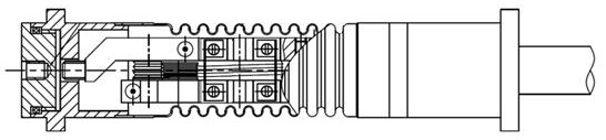
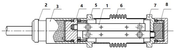
[0026] Such as image 3 As shown, a large-range differential resistance strain gauge includes end components, a protective shell, a tail component and a differential sensing structure 1 connected in sequence. The differential induction structure 1 is fixed in the protective casing, and the front end and rear end of the differential induction structure 1 are respectively connected with the end assembly and the tail assembly.

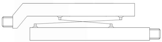
[0027] Such as Figure 4 As shown, the differential induction structure 1 includes a front differential steel wire 11 , a rear differential steel wire 12 , an upper structural member 9 and a lower structural member 10 .

[0028] Both the upper structural part 9 and the l...


PUM


Abstract

The invention discloses a wide-range differential resistance type strain gauge, which comprises an end part assembly, a protective shell with a built-in differential induction structure and a tail part assembly which are connected in sequence, and is characterized in that the differential induction structure comprises an upper structural member connected with the end part assembly and a lower structural member connected with the tail part assembly, the upper structural member and the lower structural member are sequentially arranged from top to bottom to form a structural member group, the differential induction structure further comprises a front differential steel wire and a rear differential steel wire, the front differential steel wire and the rear differential steel wire are located on the front face and the back face of the structural member group respectively and are arranged in an X-symmetry mode, the two ends of the front differential steel wire are fixed to the front side face of the upper structural member and the front side face of the lower structural member respectively, the two ends of the rear differential steel wire are fixed to the rear side faces of the upper structural member and the lower structural member respectively, and the length of the upper structural member and the length of the lower structural member are both larger than the scale distance of the wide-range differential resistance type strain gauge. According to the invention, parameters are accurate, the measuring range is convenient to adjust, the differential sensing structure is universal, and the full-range strain output range is large.

Description

technical field [0001] The invention relates to a large-range differential resistance strain gauge, which belongs to the technical field of strain gauges. Background technique [0002] The differential resistance strain gauge has the characteristics of simple structure and long-term stability, and is widely used in the field of strain monitoring of geotechnical engineering and other structures. [0003] Existing differential resistance strain gauges such as figure 1 As shown, it is generally composed of an end, a protective shell, a differential induction structure and a tail, wherein the differential induction structure is assembled by a differential steel wire and corresponding structural parts, see figure 2 . The deformation of the measured structure causes the deformation of the differential steel wire through the welding of the end and tail flanges and the tested structure, so as to obtain the change of the sum of the differential steel wire resistance and its ratio,...

Claims


Application Information

Patent Timeline
Patent Type & Authority Applications(China)
IPC IPC(8): G01B7/16
CPCG01B7/18
Inventor 夏明傅罗真胡波凌骐郑水华李杰崔岗沈祥陈彤章立宗姜文东邵炜平张锋明廖海林赵峰倪宏宇冯炳周艳和
Owner STATE GRID ELECTRIC POWER RES INST
Why Eureka
Try Eureka