
Quick release push rod with high transmission efficiency

A transmission efficiency and fast technology, applied in the direction of electric components, mechanical energy control, electrical components, etc., can solve the problems of torsion spring wear of the clutch sleeve or gear assembly, inconvenient retraction of the push rod, etc., to reduce energy consumption and improve use The effect of life and reducing the degree of wear

Pending Publication Date: 2021-04-27
ZHEJIANG JIECHANG LINEAR MOTION TECH
View PDF0 Cites 0 Cited by
  • Summary
  • Abstract
  • Description
  • Claims
  • Application Information

AI Technical Summary

Problems solved by technology

[0003] However, when the torsion spring self-locking is used, when the push rod is retracted under no load or low load, since the interference amount of the torsion spring installation remains unchanged, there will still be a large gap between the clutch sleeve or the gear assembly and the torsion spring. wear, resulting in inconvenient retraction of the pushrod

Method used


Image

  • Quick release push rod with high transmission efficiency
  • Quick release push rod with high transmission efficiency
  • Quick release push rod with high transmission efficiency

Examples


Embodiment 1

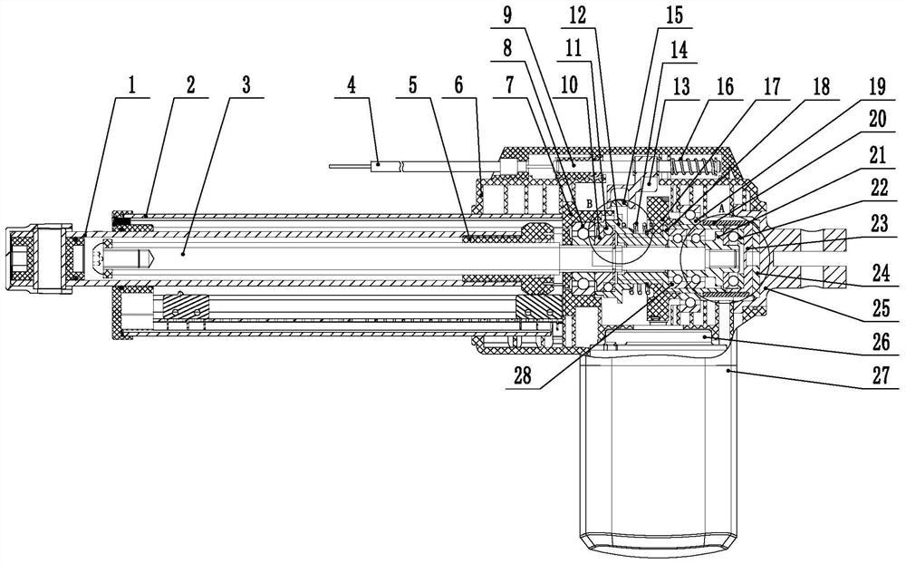
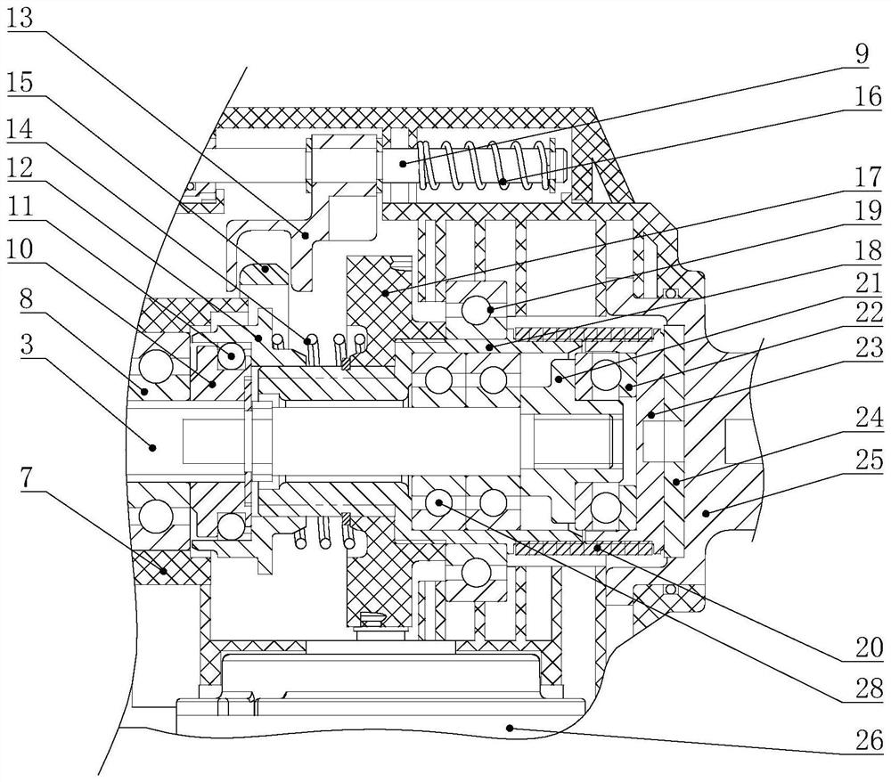
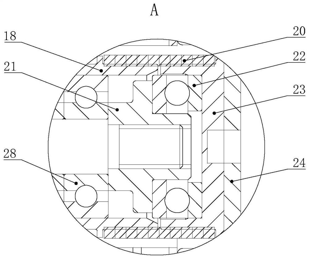
[0032] Such as Figure 1 to Figure 6 As shown, the preferred structure of the quick release push rod with high transmission efficiency in this embodiment includes a gearbox 6, a worm gear 17, a left connecting piece 10, a right connecting piece, a clutch sleeve 12 and a screw mandrel 3, and the left connecting piece 10 is connected to the The screw rod 3 is connected, the right connecting piece is relatively fixed to the worm wheel 17, the clutch sleeve 12 and the right connecting piece keep moving relative to each other in the axial direction and relatively fixed in the circumferential direction, and the clutch sleeve 12 moves axially to Combined with or separated from the left connecting piece 10, the clutch sleeve 12 keeps moving relative to the axial direction and relatively fixed in the circumferential direction when combined with the left connecting piece 10, the gear box 6 is provided with a friction plate 24, the When the quick release push rod bears a static load, the...

Embodiment 2

[0051] The difference between this embodiment and Embodiment 1 is that in this embodiment, the screw rod 3 is nested in the connecting seat 18, and a rolling element is arranged in the connecting seat 18, and the surface of the screw rod 3 is in contact with the connecting seat 18. The above-mentioned rolling parts are rolled and fitted, wherein, the rolling parts can be balls, cylinders, cones and other rolling parts. In this implementation, the rolling parts are preferably balls. In this way, the screw mandrel 3 can contact the connecting seat 18 through the balls to realize mutual positioning, and can axially slide relative to the connecting seat 18 so that the axial force exerted by the load on it can be transmitted to the torsion spring seat 23, and this embodiment can also achieve the technical effect described in the first embodiment.


PUM


Abstract

The invention provides a quick release push rod with high transmission efficiency and belongs to the field of quick release push rods. The quick release push rod comprises a gear box, a worm gear, a left connecting piece, a right connecting piece, a clutch sleeve and a lead screw, wherein the left connecting piece is connected with the lead screw, the right connecting piece and the worm gear are relatively fixed, and the clutch sleeve and the right connecting piece keep axial relative movement and are relatively fixed in the circumferential direction; the clutch sleeve axially moves to be combined with or separated from the left connecting piece, the clutch sleeve and the left connecting piece keep axial relative movement and are relatively fixed in the circumferential direction when combined, a friction plate is arranged on the gear box, and when the quick release push rod bears static loads, the right connecting piece and the friction plate are matched to achieve self-locking. The self-locking quick release push rod is advantaged in that by adopting the structure, the push rod can be retracted more conveniently, and the self-locking quick release push rod is used for self-locking of the quick release push rod.

Description

【Technical field】 [0001] The invention relates to a quick release push rod with high transmission efficiency and belongs to the field of quick release push rods. 【Background technique】 [0002] The quick release push rod is a kind of electric push rod that can realize quick release. Usually, a clutch sleeve is set between the gear assembly and the screw rod. When the clutch sleeve is connected with the gear assembly and the screw rod at the same time, the gear assembly and the screw rod can be For transmission, when the movement of the clutch sleeve is separated from the screw rod, the gear assembly and the screw rod are relatively separated and the transmission cannot be realized. The screw rod can be released quickly without the hindrance of the gear assembly. A torsion spring is arranged outside the sleeve or the gear assembly for self-locking. [0003] However, when the torsion spring self-locking is used, when the push rod is retracted under no load or under low load, ...

Claims


Application Information

Patent Timeline
IPC IPC(8): H02K7/116H02K7/108
CPCH02K7/108H02K7/1166
Inventor 张昭
Owner ZHEJIANG JIECHANG LINEAR MOTION TECH
Learn More