Self-starting three-phase synchronous reluctance motor

A reluctance motor, three-phase synchronous technology, applied in the direction of synchronous motors, electric components, electrical components, etc. for single-phase current, can solve problems such as difficult online start, motor operation disturbance, motor slip, etc., and achieve starting speed The effect of speeding up and expanding the range of use

Inactive Publication Date: 2021-04-27
CRRC YONGJI ELECTRIC CO LTD
View PDF15 Cites 1 Cited by
  • Summary
  • Abstract
  • Description
  • Claims
  • Application Information

AI Technical Summary

Problems solved by technology

[0003] Although the synchronous reluctance motor has many advantages, its disadvantages are also obvious. At present, there are still many problems that need to be studied and solved: (1) There is no starting winding on the rotor, so it is difficult to start directly online; (2) The synchronous reluctance motor Excitation current must be passed in during operation, so that its power factor is limited
(3) The magnetic circuit saturation of the AC-D axis of the synchronous reluctance motor is not only affected by the coaxial current but also the current of the phase-orthogonal axis, which makes the control of the synchronous reluctance motor face some special problems; (4) The process of the motor running There is an unstable interval in the frequency converter, and the harmonic components in the frequency converter will disturb the operation of the motor, causing the motor to slip in a small period of time

Method used


Image

  • Self-starting three-phase synchronous reluctance motor
  • Self-starting three-phase synchronous reluctance motor

Examples


Embodiment Construction

[0016] The present invention will be further described below in conjunction with specific examples.

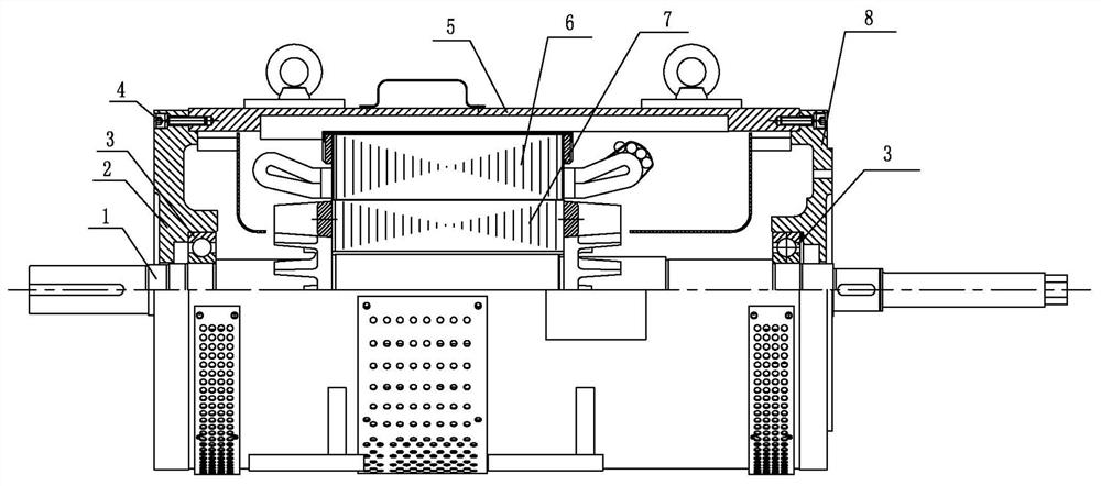
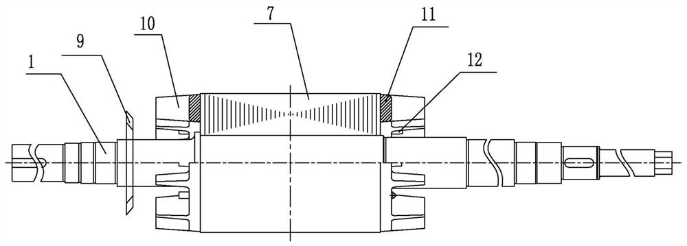
[0017] A self-starting three-phase synchronous reluctance motor, such as figure 1 and figure 2 Shown: includes a rotor structure, the rotor structure includes a rotating shaft 1, the outer periphery of the middle part of the rotating shaft 1 is wound with a rotor core 7, and the outer periphery of the rotor iron core 7 is wound with a stator coil 6; the outer periphery of the stator coil 6 is a machine Seat 5, the front end of the base 5 is matched with a front end cover 8, and the rear end is matched with a rear end cover 2, and the front end cover 8 and the rear end cover 2 are all assembled on the rotating shaft 1 through a bearing 3; the front end Both the cover 8 and the rear end cover 2 are connected to the machine base 5 through bolts 4; the rotor structure also includes a rotor fan 9 and a cast aluminum guide bar 10, and the rotor fan 9 is installed on the rotating s...


PUM


Abstract

The invention discloses a self-starting three-phase synchronous reluctance motor, and relates to the field of reluctance motors. The motor comprises a rotor structure, which comprises a rotating shaft, wherein a rotor iron core is wound on the periphery of the middle of the rotating shaft, a stator coil is wound on the periphery of the rotor iron core, a base is arranged on the periphery of the stator coil, a front end cover is fittingly mounted at the front end of the base, a rear end cover is fittingly mounted at the rear end of the base, the front end cover and the rear end cover are assembled on the rotating shaft through bearings, the front end cover and the rear end cover are connected with the base through bolts, the rotor structure further comprises a rotor fan and cast aluminum guide bars, the rotor fan is installed on the rotating shaft and located on the rear side of the rotor iron core, pressing plates are fixed to the front end and the rear end of the rotor iron core, rectangular magnetic barriers and tooth grooves are formed in magnetic shoe part of the rotor iron core, the cast aluminum guide bars are arranged in the rectangular magnetic barriers and the tooth grooves, and balance blocks are further fixedly arranged at the two ends of the rotor iron core. According to the invention, the motor has self-starting capability and can reach a stable state under the condition of power supply of a three-phase alternating-current sinusoidal power supply.

Description

technical field [0001] The invention relates to the field of reluctance motors, in particular to a self-starting three-phase synchronous reluctance motor. Background technique [0002] Compared with the traditional DC motor, the synchronous reluctance motor has no brushes and slip rings, and the maintenance is simple and convenient. Compared with the asynchronous machine, there is no winding on the rotor of the synchronous reluctance motor, so there is no rotor copper loss, basically there is no problem of rotor heating, which improves the operating efficiency and safety of the motor. In addition, because there is no additional winding on the rotor, the motor response is not affected The rotor time constant is limited, and the dynamic response speed is fast. Compared with the switched reluctance motor, the synchronous reluctance motor can achieve smooth rotation surface and relatively continuous reluctance change, which avoids the problems of torque ripple and large noise d...

Claims


Application Information

Patent Timeline
Patent Type & Authority Applications(China)
IPC IPC(8): H02K19/10H02K19/14H02K29/03H02K7/10H02K1/22H02K1/26
CPCH02K19/10H02K19/14H02K29/03H02K7/10H02K1/22H02K1/26
Inventor 刘瑞强黄新宇南振江雷晓林
Owner CRRC YONGJI ELECTRIC CO LTD
Why Eureka
Try Eureka