A self-energy leakage monitoring method and system based on leakage current

A technology of leakage monitoring and leakage current, which is applied in the field of self-energy leakage monitoring based on leakage current, can solve the problems of continuous energy supply, loss of external power supply, high equipment cost, etc., and achieve self-starting and avoid electric leakage and electric shock , the effect of simple implementation method

Active Publication Date: 2021-04-20
YUNNAN POWER GRID CO LTD ELECTRIC POWER RES INST
View PDF2 Cites 0 Cited by
  • Summary
  • Abstract
  • Description
  • Claims
  • Application Information

AI Technical Summary

Problems solved by technology

The traditional CT method of power acquisition has a high energy conversion rate and is easy to obtain power, but the energy acquisition is unstable; due to the lack of electrical isolation, there are certain safety hazards in the capacitor voltage division power acquisition; the laser power acquisition output has high output accuracy and stable energy supply, but the cost is relatively high. High; photovoltaic cells are a renewable energy source that does not produce greenhouse gases, but is easily affected by the external environment and cannot achieve continuous energy supply; ultrasonic electricity is relatively safe and reliable, but the equipment cost is high, and the conversion rate of ultrasonic electric energy is relatively low. Low; microwave radiation type power acquisition can realize long-distance wireless power transmission, with good orientation, but low transmission efficiency and high cost
[0005] With the continuous innovation and progress of technology, the power-taking device and method are also constantly improving. Among them, the patent number is 201810571411.4 for a high-power capacitor power-taking device and method. The proposed voltage-dividing capacitor power-taking method removes PT, adopts Capacitors take power and use supercapacitors or batteries to store energy. In addition to isolating the power-taking circuit and subsequent working circuits, this method is also affected by various factors such as temperature, humidity and stray capacitance, and the output power is limited.
The patent No. 201910138276.9 is a Rogowski coil-based inductive power pick-up device for transmission lines. It uses the principle of transformers to convert the energy on part of the high-voltage wires into electric energy output. This method is difficult to output power smoothly within the large current range of the transmission line. , usually when the current of the transmission line is small, the output power is insufficient, and when the current of the transmission line is large, the output power is too high, and the power-taking device heats up seriously
[0006] To sum up, on the one hand, the current leakage monitoring equipment is mainly powered by an external power supply, there is a risk of electric shock and equipment malfunction caused by the leakage of the external power supply, and the external power supply itself has a certain loss; on the other hand, online monitoring equipment and other smart The problem of power supply of equipment, in the prior art, it is mostly used to take power from the transmission line

Method used


Image

  • A self-energy leakage monitoring method and system based on leakage current
  • A self-energy leakage monitoring method and system based on leakage current
  • A self-energy leakage monitoring method and system based on leakage current

Examples


Embodiment Construction

[0037] In order to make the purpose, technical solution and advantages of the present application clearer, the technical solution of the present application will be clearly and completely described below in conjunction with specific embodiments of the present application and corresponding drawings.

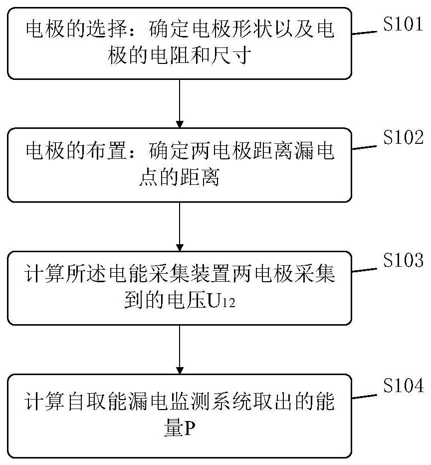
[0038] refer to figure 1 , which is a flow chart of a self-energy leakage monitoring method based on leakage current provided by this application, the steps are as follows:

[0039] S101, selection of electrodes: determining the shape of the electrodes and the resistance and size of the electrodes;

[0040] S102, electrode arrangement: determine the distance between the two electrodes and the leakage point;

[0041]S103, calculate the voltage U collected by the two electrodes of the electric energy collection device 12 ;

[0042] S104. Calculate the energy P extracted by the self-energy leakage monitoring system.

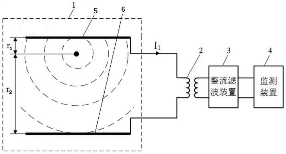
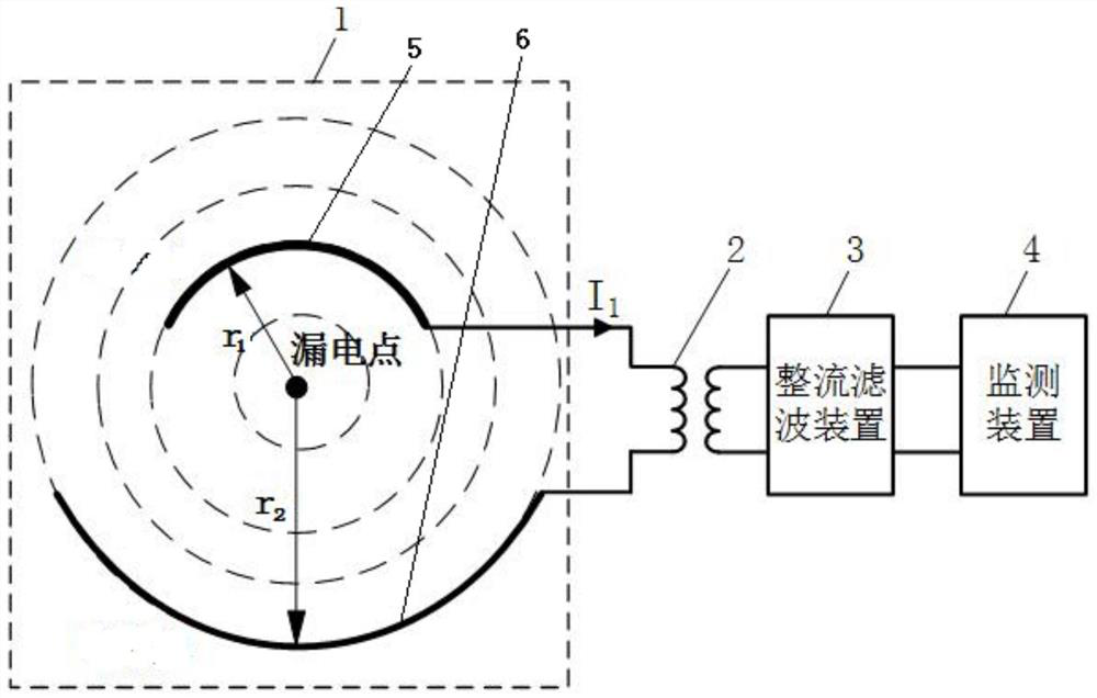
[0043] refer to figure 2 , image 3 , Figure 4 , is a sch...


PUM


Abstract

The embodiment of the present application discloses a self-energy leakage monitoring method based on leakage current, including: step 1: selection of electrodes; step 2: arrangement of electrodes; step 3: calculation of the voltage collected by the two electrodes of the electric energy collection device u 12 ; Step 4: Calculate the energy P extracted by the self-energy leakage monitoring system; the method is applied to a self-energy leakage monitoring system based on leakage current, and the system includes: an electric energy collection device 1, an isolation transformer 2, a rectification filter Device 3 and monitoring device 4; the power collection device includes electrode I5 and electrode II6 to collect leakage current signals of power equipment or transmission lines, the power collection device is connected in series with the primary side of the isolation transformer, and the power collection device collects After the alternating current is processed by the isolation transformer and the rectification and filtering device, it provides a stable driving power for the monitoring device.

Description

technical field [0001] The present application relates to the technical field of electricity harvesting for on-line monitoring of electric power systems, and in particular to a leakage monitoring method and system for self-energy harvesting based on leakage current. Background technique [0002] Leakage accidents in my country's low-voltage distribution network occur frequently. Electrical fires, electrical equipment damage, and human body electric shocks have seriously affected production and life, threatening the safety of life and property. There are many existing methods for detecting leakage current, such as small resistance sampling method, Hall sensor current detection method, current transformer measurement method, current comparator and so on. Among them, the more commonly used small resistance sampling method is to connect a resistor in series in the original circuit, convert the current signal into a voltage signal, and obtain the leakage current signal by directl...

Claims


Application Information

Patent Timeline
Patent Type & Authority Patents(China)
IPC IPC(8): G01R31/52
CPCG01R31/50
Inventor 刘红文唐伟超王科孙亚洲张春丽杨金东
Owner YUNNAN POWER GRID CO LTD ELECTRIC POWER RES INST
Why Eureka
Try Eureka