Roller nail recoil type nail puller for high-pressure roller mill

A high-pressure roller grinding and nail puller technology, which is applied in metal processing, metal processing equipment, manufacturing tools, etc., can solve the problem of high flatness requirements on the upper and lower edges of the coaxiality sleeve of the middle part, and the easy generation of screw-type nail pullers. The problems of rust jamming failure and high manufacturing precision requirements of screw-type nail pullers can achieve the effect of reducing costs and labor intensity of workers, good welding effect and low cost.

Pending Publication Date: 2021-04-30
广西钢铁集团有限公司 +1
View PDF1 Cites 0 Cited by
  • Summary
  • Abstract
  • Description
  • Claims
  • Application Information

AI Technical Summary

Problems solved by technology

There are several disadvantages in this design. First, the nut needs to be twisted several times in a row, which is time-consuming, low in efficiency, and labor-intensive; The nut is reheated after reheating; the third is that the manufacturing precision of the screw-type nail puller is high, the coaxiality of the middle part and the flatness of the upper and lower edges of the sleeve are high, and it is difficult to make it by hand on site, and it needs to be made by a processing workshop; the fourth is to use the sleeve to be able to To withstand the roller skin between the densely distributed roller nails, it is required to have a small diameter, small thickness, weak sleeve strength, and easy deformation; fifth, the fine screw-type nail puller is prone to rust, jamming, and failure, especially in conditions poor production site

Method used


Image

  • Roller nail recoil type nail puller for high-pressure roller mill
  • Roller nail recoil type nail puller for high-pressure roller mill
  • Roller nail recoil type nail puller for high-pressure roller mill

Examples


Embodiment 1

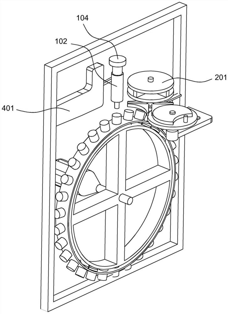
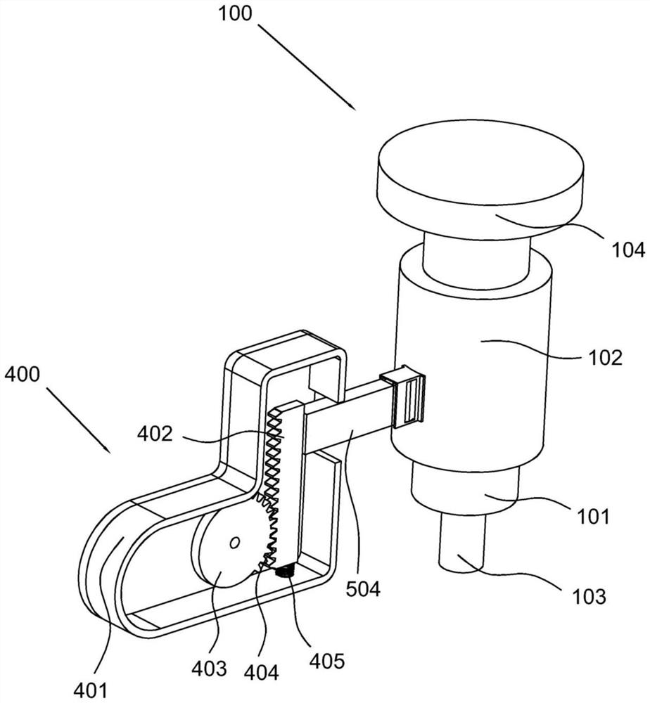
[0035] refer to Figure 1-5 , a high-pressure roller mill roller nail recoil type nail puller, comprising, a nail pulling assembly 100, including a nail pulling middle tube 101, a sleeve 102 set outside the nail pulling middle tube 101, and a nail pulling middle tube The nail-pulling shaft 103 at the end of 101, the nail-pulling middle tube 101 rear end is provided with a stopper 104; the nail-pulling preparation assembly includes a grinding head arranged near the roller nail ring, and a roller nail placed near the roller nail ring The spray gun and the gluing part arranged near the spray gun, the roller nail ring is provided with a position replacement part 200 for driving the gluing part and spray gun position selection; and the driving assembly 400, the driving assembly 400 is arranged at the nail pulling assembly 100 .

[0036] Specifically, the body of the present invention includes a nail-pulling assembly 100. In this embodiment, the nail-pulling assembly 100 is arranged ...

Embodiment 2

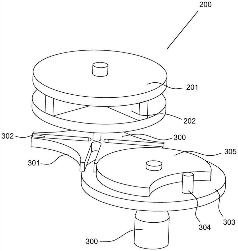
[0041] refer to Figure 1-5 , This embodiment is different from the first embodiment in that: the position replacement part 200 includes a rotary disk 201, a storage groove 202 opened on the outer wall of the rotary disk 201, and a sliding block 203 arranged in the storage groove 202, wherein, Spray gun and gluing part are connected on the sliding block 203 respectively, and the notch place of storage tank 202 is connected with switch plate 204 along the vertical direction sliding, and the rear end of sliding block 203 is provided with the electric motor that drives sliding block 203 to slide. Cylinder 205, the lower end of switch plate 204 is provided with the first slope, and the front end of sliding block 203 protrudes outwards to have drive plate 206, and drive plate 206 is provided with inclined plate 207 near the side wall both sides of storage tank 202, and is set on the inclined plate 207 There is a second inclined surface corresponding to the first inclined surface, a...

Embodiment 3

[0048] refer to Figure 1-5 , This embodiment is different from the above embodiments in that: the driving assembly 400 includes a starting cylinder 401 arranged near the sleeve 102, a rack 402 slidingly connected in the starting cylinder 401 in the vertical direction, and a rack 402 rotatably connected in the starting cylinder 401 The driving wheel 403 in 401, wherein, the driving wheel 403 is provided with a gear tooth 404, and the gear tooth 404 is provided at a position on a quarter of the driving wheel 403, and a driving tooth is provided between the lower end of the rack 402 and the starting cylinder 401. The spring 405 that the bar 402 moves up, the rack 402 protrudes outwards and the connecting rod is connected with the sleeve 102, the lower end of the middle tube 101 protrudes outwards with a flanging, and the flanging is provided with a ring groove that matches the sleeve 102 , a connecting buckle 500 protrudes outward from the side wall of the sleeve 102, a card edg...


PUM


Abstract

The invention discloses a roller nail recoil type nail puller for a high-pressure roller mill. The roller nail recoil type nail puller comprises a nail pulling assembly, a nail pulling preparation assembly and a driving assembly, wherein the nail pulling assembly comprises a nail pulling middle pipe, a sleeve arranged outside the nail pulling middle pipe in a sleeving manner, and a nail pulling shaft arranged at the end of the nail pulling middle pipe, and a stop block is arranged at the rear end of the nail pulling middle pipe; the nail pulling preparation assembly comprises a grinding head arranged at the position close to a roller nail ring, spray guns arranged at the position close to a roller nail on the roller nail ring, and gluing pieces arranged at the position close to the spray gun, and the roller nail ring is provided with a position replacement part used for driving the gluing pieces and the spray guns to select positions; and the driving assembly is arranged at the position of the nail pulling assembly.

Description

technical field [0001] The invention relates to the technical field of high pressure roller mill maintenance, in particular to a high pressure roller mill roller nail recoil type nail puller. Background technique [0002] The high-pressure roller mill is a new type of energy-saving crushing and grinding equipment. After the material is fed, the gap between the static and moving rollers is opened, and between the static and moving rollers moving in opposite directions, it is "broken" under the high pressure of the hydraulic mechanism. In order to improve the service life of the static and dynamic rollers of the high-pressure roller mill, cylindrical holes are generally equidistantly opened on the roller skin, and the bottom of the hole is a hemisphere. Protrude the roller skin by about 5-10mm, so that during operation, an accumulation of material can be formed between the roller nails to protect the roller skin, and the roller nails can be replaced regularly after wear. [0...

Claims


Application Information

Patent Timeline
Patent Type & Authority Applications(China)
IPC IPC(8): B23P19/02
CPCB23P19/02
Inventor 张中中吴丹伟吴军平韦立峰戴鑫杰陈连伟徐群建王雷雷朱新海黎应君杨德宏
Owner 广西钢铁集团有限公司
Why Eureka
Try Eureka