
Clamping and drilling device

A technology of drilling device and clamping rod, which is applied in the field of mechanical processing

Inactive Publication Date: 2021-04-30
郑斗
View PDF7 Cites 1 Cited by
  • Summary
  • Abstract
  • Description
  • Claims
  • Application Information

AI Technical Summary

Problems solved by technology

[0003] The purpose of the embodiment of the present invention is to provide a clamping drilling device, aiming at solving the problem of needing to clamp separately

Method used


Image

  • Clamping and drilling device
  • Clamping and drilling device
  • Clamping and drilling device

Examples


Embodiment Construction

[0018] In order to make the object, technical solution and advantages of the present invention clearer, the present invention will be further described in detail below in conjunction with the accompanying drawings and embodiments. It should be understood that the specific embodiments described here are only used to explain the present invention, not to limit the present invention.

[0019] The specific implementation of the present invention will be described in detail below in conjunction with specific embodiments.

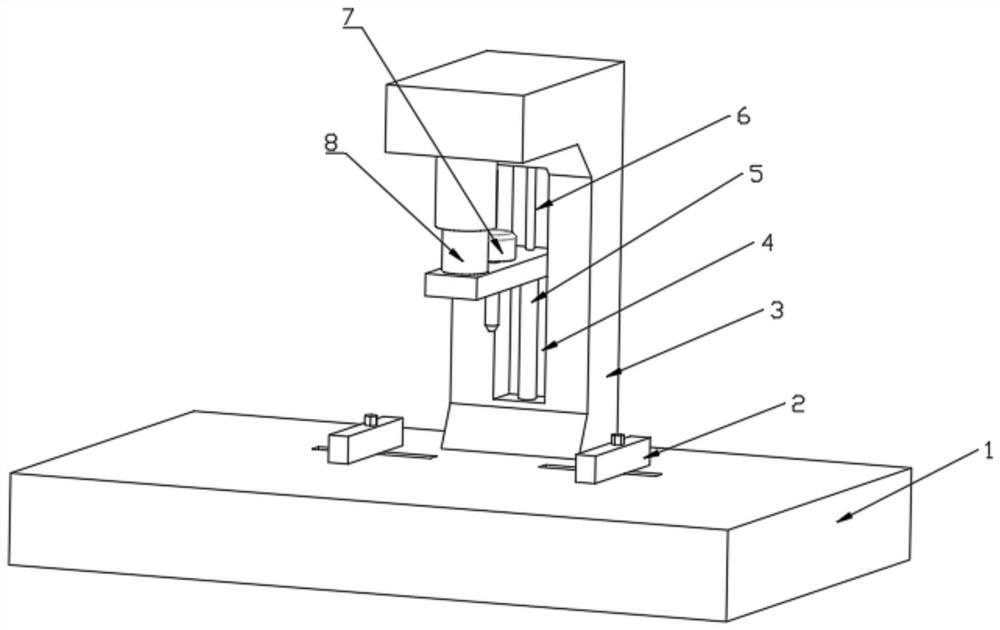
[0020] Such as figure 1 As shown, it is a structural diagram of a clamping drilling device provided by an embodiment of the present invention, including:

[0021] Base 1 for support and installation;

[0022] The support frame 3 is installed on the base 1;

[0023] The drilling part 7 is slidably mounted on the support frame 3 for drilling;

[0024] The lifting driving part is installed on the support frame 3 and is connected with the drilling part 7 for driv...


PUM


Abstract

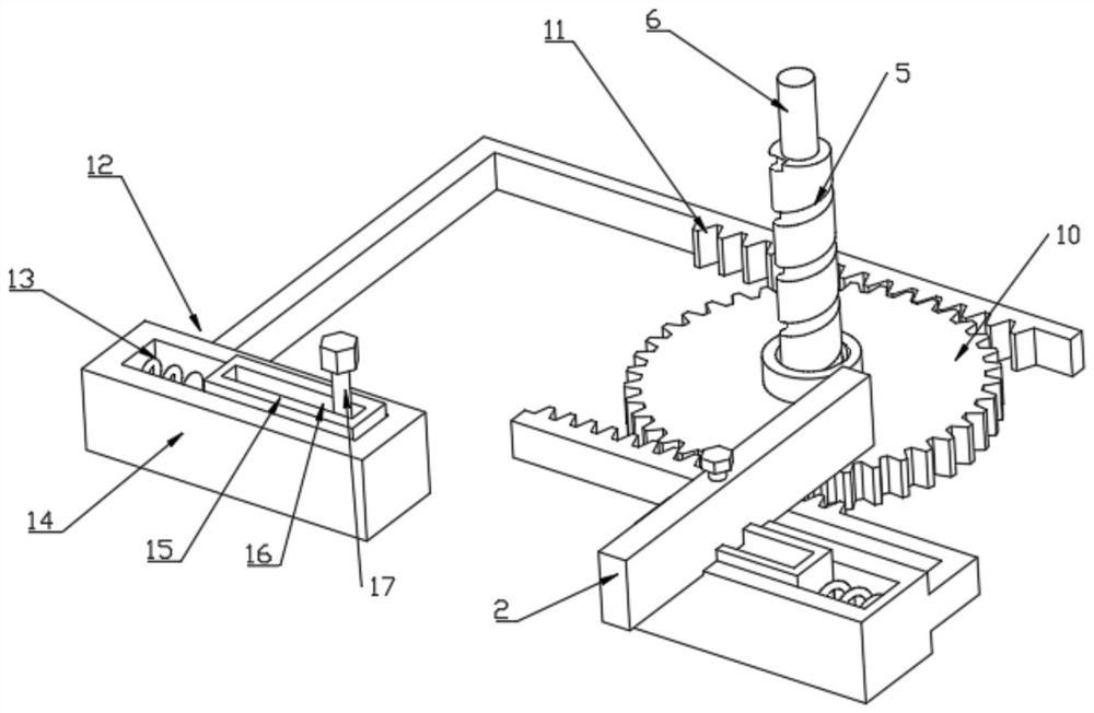
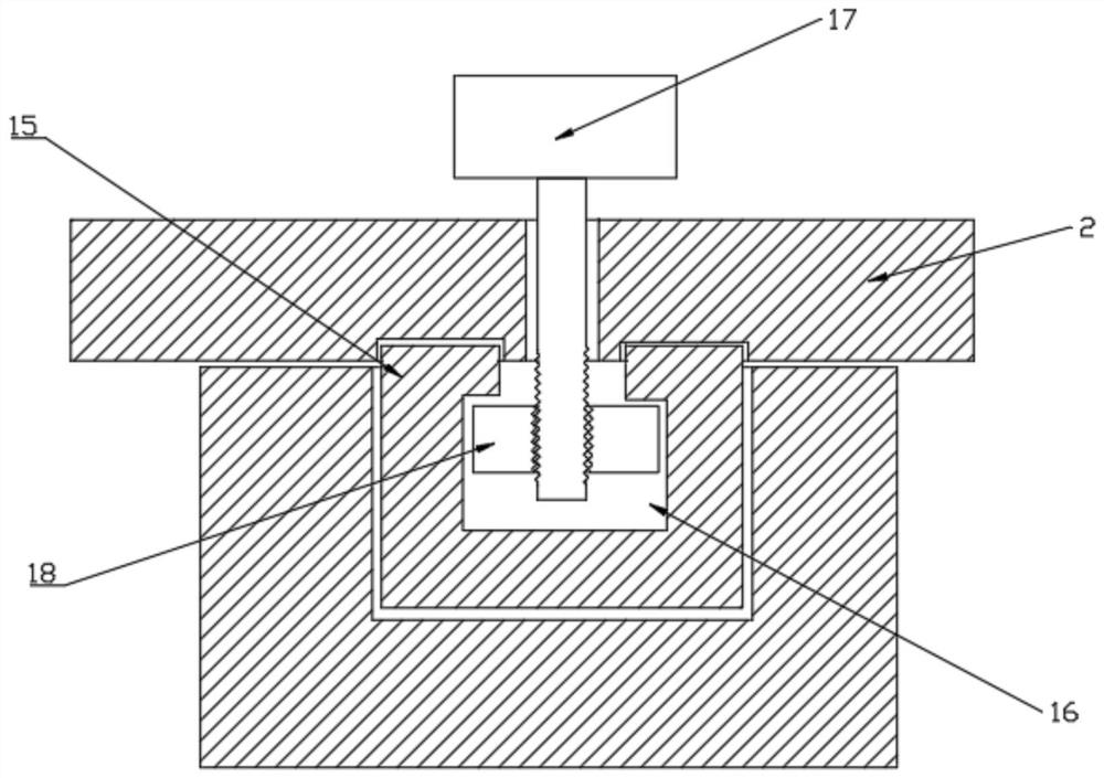
The invention is applicable to the technical field of machining, and provides a clamping and drilling device. The clamping and drilling device comprises a base, a supporting frame, a drilling piece mounted on the supporting frame in a sliding manner, a lifting driving piece installed on the supporting frame and connected with the drilling piece, a gear rotationally arranged in the base, a screw groove rod fixedly connected to the drilling piece and nested at the axis position of the gear in a cooperation manner and a sliding piece, wherein racks are arranged on the two sides of the gear in an engaged manner, and the sliding piece is connected to the racks and connected with a clamping rod. The lifting driving piece drives the drilling piece to descend, the drilling piece drives the screw groove rod to move downwards, the screw groove rod drives the gear to rotate, the gear rotates to drive the racks to slide, the racks pull the sliding piece and the clamping rod to get close to conduct clamping, and the drilling piece conducts drilling. The lifting driving piece drives the drilling piece to be lifted, the screw groove rod is lifted to drive the gear to rotate reversely, and the sliding piece is pulled to be separated from the clamping rod. The clamping and drilling device has the advantages of being simple in structure, convenient to operate, capable of saving energy, high in drilling quality and convenient to popularize and implement.

Description

technical field [0001] The invention belongs to the technical field of mechanical processing, and in particular relates to a clamping drilling device. Background technique [0002] With the development of society and the advancement of science and technology, the machinery industry has developed rapidly. For machining, various holes are arranged on the components. The components can be plate-like structures or other irregular components. When drilling When the parts need to be drilled, the parts need to be fixed and then drilled. The hole process is a process that is often involved in machining. Generally, the workpiece is fixed first and then drilled. However, in During the drilling process, due to the shaking of the workpiece, the drilling tilt or the hole diameter changes, making the entire workpiece a defective product, wasting resources and time; increasing the preparation time for processing, increasing the workload, and reducing the utilization rate. Contents of the...

Claims


Application Information

Patent Timeline
IPC IPC(8): B23Q3/06B23Q5/26
CPCB23Q3/06B23Q5/26
Inventor 郑斗
Owner 郑斗
Learn More