Mask welding equipment

A welding equipment and mask technology, applied in the field of mask welding equipment, can solve problems such as troublesome use of staff, limited rotation speed, easy angle change, etc., and achieve the effects of easy maintenance and maintenance, stable steering angle, and simple and stable structure.

Inactive Publication Date: 2021-04-30
江西企事通医疗器械有限公司
View PDF11 Cites 0 Cited by
  • Summary
  • Abstract
  • Description
  • Claims
  • Application Information

AI Technical Summary

Problems solved by technology

[0003] Traditional mask welding equipment uses a servo motor to drive the clamping cylinder or finger cylinder to rotate, thereby driving the finger cylinder or clamping cylinder to move the ear straps to the top of the mask. The steering mechanism of the traditional finger cylinder or clamping cylinder is more complicated, maintenance and The maintenance cost is high, and it is also prone to angle changes, and the rotation speed is also limited by the inertial force. Further improvements can be made to improve the rotation stability and speed of the finger cylinder or clamping cylinder. In addition, the welding head is welded after welding. Finally, the surface sometimes sticks to the fiber of the ear strap, and the fiber will melt on the surface of the welding head when heated, affecting the welding quality. The traditional method is manual cleaning, which is troublesome and can be further improved. In addition, the traditional mask welding equipment It is inconvenient to adjust the tension control mechanism of the ear hanging rope, which brings some troubles to the staff, and further improvement can be made

Method used


Image

  • Mask welding equipment
  • Mask welding equipment
  • Mask welding equipment

Examples


Embodiment Construction

[0035] In order to further illustrate the various embodiments, the present invention provides accompanying drawings, which are part of the disclosure of the present invention, and are mainly used to illustrate the embodiments, and can be used to explain the operating principles of the embodiments in conjunction with the relevant descriptions in the specification, for reference Those of ordinary skill in the art should be able to understand other possible implementations and advantages of the present invention. The components in the figures are not drawn to scale, and similar component symbols are generally used to represent similar components.

[0036] According to an embodiment of the present invention, a mask welding device is provided.

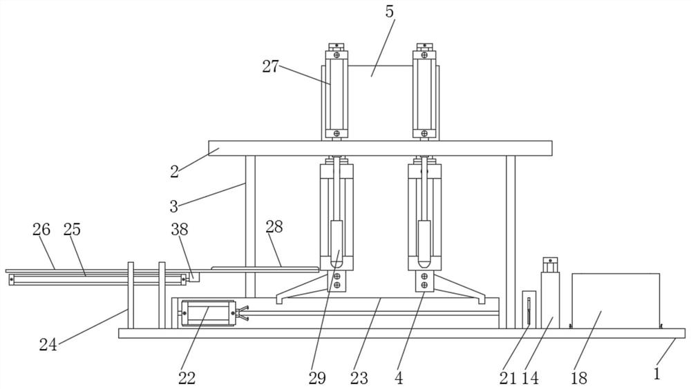
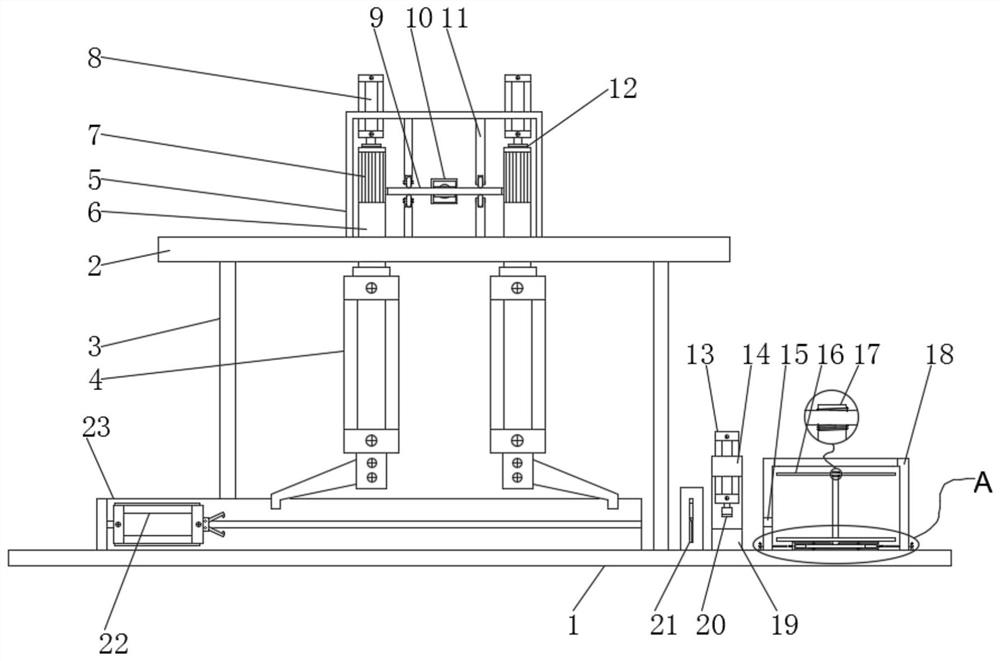
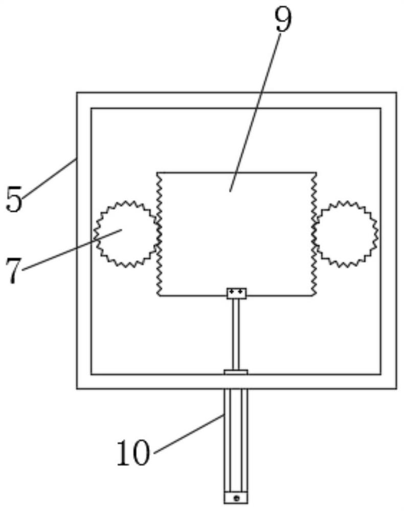
[0037]Now in conjunction with accompanying drawing and specific embodiment the present invention is further described, as Figure 1-8 As shown, a mask welding equipment according to an embodiment of the present invention includes an operati...


PUM


Abstract

The invention discloses mask welding equipment. The mask welding equipment comprises an operation plate and a top plate, wherein the top plate is fixedly mounted above the operation plate through stand columns, a top box is fixedly mounted on the top face of the top plate, a fifth air cylinder is fixedly mounted in front of the front vertical face of the top box, a piston rod of the fifth air cylinder penetrates through the top plate to be connected to a welding head, a first air cylinder is fixedly connected to the top face of the top box in a penetrating mode, a gear column is rotatably connected to the bottom face of the piston rod of the first air cylinder through a first axial rotating base, a connecting shaft is fixedly connected to the bottom face of the gear column, penetrates through the top plate and is slidably connected to the top plate. The mask welding equipment has the beneficial effects that steering of the first finger air cylinder is completed through the second air cylinder, the structure is simple and stable, repairing and maintaining are convenient, the production cost is lower, meanwhile, the stroke of the second air cylinder is stable, the steering angle of the first finger air cylinder is stabler, in addition, the second air cylinder responds rapidly, therefore the rotating speed of the first finger air cylinder is increased, and furthermore, the production efficiency is improved.

Description

technical field [0001] The invention relates to the technical field of mask production, in particular to a mask welding equipment. Background technique [0002] A mask is a kind of sanitary product, which generally refers to being worn on the mouth and nose to filter the air entering the mouth and nose, so as to block harmful gases, odors, droplets, viruses and other substances. It is made of gauze or paper, etc. It has a certain filtering effect on the air entering the lungs. When respiratory infectious diseases are prevalent, when working in dusty and other polluted environments, wearing a mask has a very good effect. The mask is equipped with ear straps, which are generally welded on the The edge of the mask. [0003] Traditional mask welding equipment uses a servo motor to drive the clamping cylinder or finger cylinder to rotate, thereby driving the finger cylinder or clamping cylinder to move the ear straps to the top of the mask. The steering mechanism of the traditio...

Claims


Application Information

Patent Timeline
Patent Type & Authority Applications(China)
IPC IPC(8): B29C65/02B29C65/74A41H42/00D06H7/02B65H67/02B65H59/38A41D13/11B29L31/48
CPCB29C65/02B29C65/74B29C66/8762A41H42/00D06H7/02B65H67/02B65H59/382A41D13/11B29L2031/4835
Inventor 章明
Owner 江西企事通医疗器械有限公司
Why Eureka
Try Eureka