Textile fabric heat pump dryer

A drying machine and textile technology, applied in the direction of drying machine, drying, progressive drying machine, etc., can solve the problems of textile pulling, textile wrinkling, affecting drying effect, etc., and achieve the goal of improving product quality and saving energy Effect

Pending Publication Date: 2021-04-30
兰建德
View PDF4 Cites 3 Cited by
  • Summary
  • Abstract
  • Description
  • Claims
  • Application Information

AI Technical Summary

Problems solved by technology

[0003] During the working process of the existing textile dryers, the textiles are easily blown up by the wind due to the strong wind force and the light textiles. First, the distance between the textiles and the air outlet increases, which affects the drying effect. To make the textiles be pulled, it is easy to cause product damage, so it is necessary to design a mechanism for the dryer to prevent the textiles from being blown up, and the existing dryers will cause the wrinkles of the textiles to a certain extent, so it is necessary to address the above problems. Drying for some improvements

Method used


Image

  • Textile fabric heat pump dryer
  • Textile fabric heat pump dryer
  • Textile fabric heat pump dryer

Examples


Embodiment 1

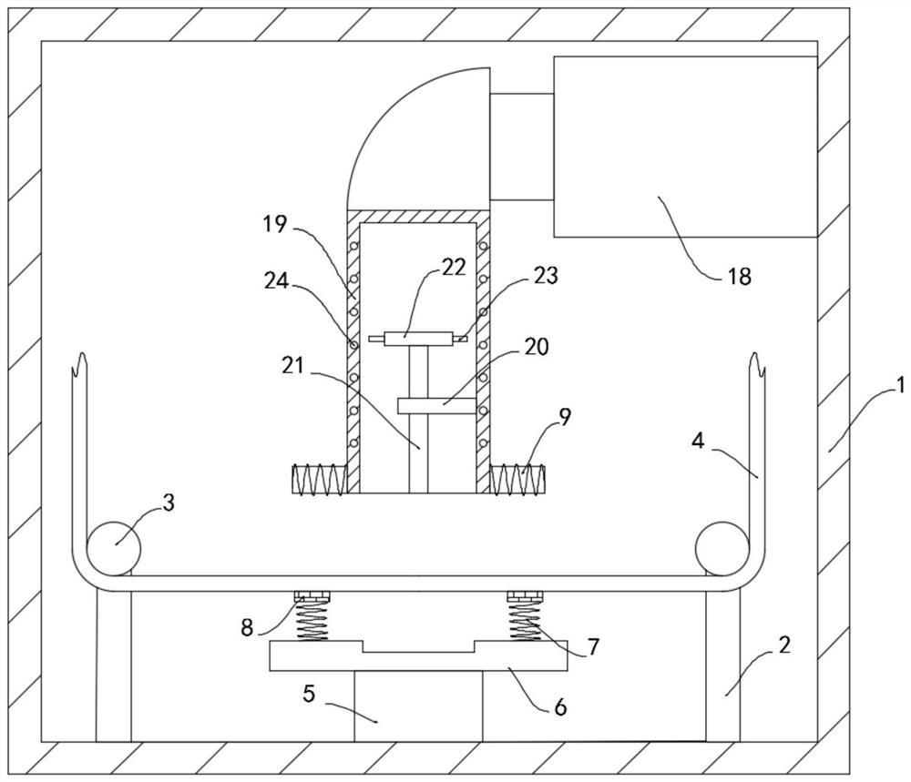
[0023] Such as figure 1 As shown, a heat pump dryer for textiles includes a drying box 1, the inner lower wall of the drying box 1 is fixedly connected with two symmetrically arranged brackets 2, and the side wall of the bracket 2 is rotatably connected with a transmission wheel 3 , the two transmission wheels 3 are jointly driven and connected with a cloth 4, the inner wall of the drying box 1 is fixedly connected with a heat pump machine 18, the side wall of the heat pump machine 18 is sealed and fixedly connected with an air outlet pipe 19, and the side wall of the air outlet pipe 19 A plurality of spiral coils 24 are embedded, and the inner side wall of the air outlet pipe 19 is fixedly connected with a support block 20, and the side wall of the support block 20 is rotatably connected with a rotating shaft 21. It should be noted that the rotating shaft 21 is connected to the supporting block 20 through a bearing. Rotationally connected, the upper end of the rotating shaft ...

Embodiment 2

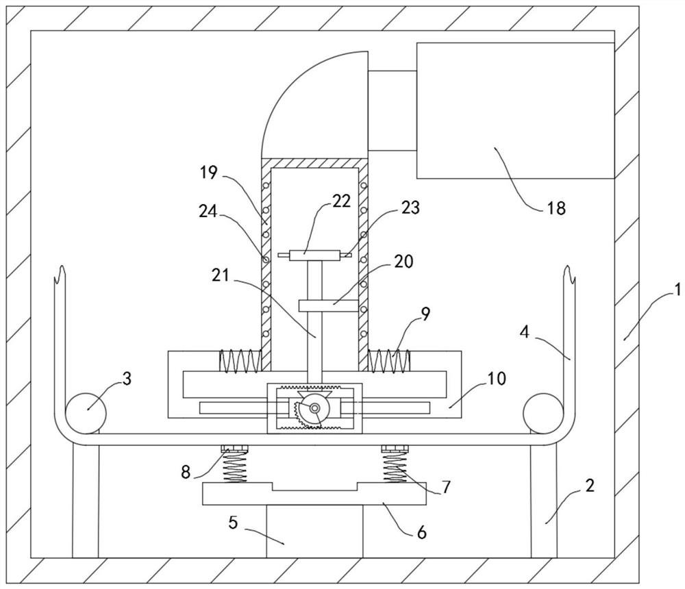
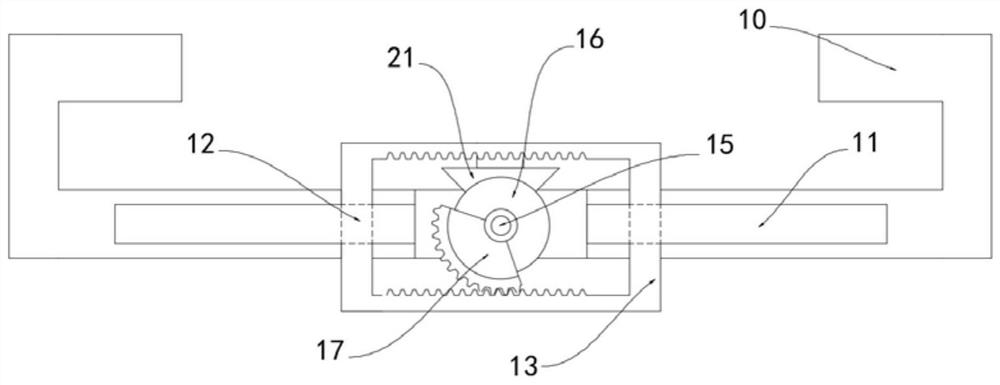
[0027] Such as Figure 2-3 As shown, the difference between this embodiment and Embodiment 1 is that: the lower end of the rotating shaft 21 is fixedly connected with the first bevel gear 14, and the two iron cores 9 are fixedly connected with the slide rail 10, and the slide rail 10 is provided with a sliding Groove 11, it is worth noting that the sliding groove 11 is coated with a smooth paint, the smooth paint is natural wood paint, two sliders 12 are slidably connected in the sliding groove 11, and the two sliders 12 are jointly fixedly connected with a push plate 13 , the push plate 13 is provided with a through hole and the inner surface is provided with a rack, the side wall of the slide rail 10 is rotatably connected with a transmission shaft 15, and the transmission shaft 15 is coaxially fixedly sleeved with a second bevel gear 16 and an incomplete gear in turn. 17. By setting the rotating shaft 21 and the second bevel gear 16, the wind energy is converted into kineti...


PUM


Abstract

The invention belongs to the field of dryers, and particularly relates to a textile fabric heat pump dryer which comprises a drying box body. Two symmetrically-arranged supports are fixedly connected to the lower wall of the inner side of the drying box body, transmission wheels are rotatably connected to the side walls of the supports, and the two transmission wheels are jointly in transmission connection with cloth. A heat pump machine is fixedly connected to the inner side wall of the drying box body, an air outlet pipe fixedly communicates with the side wall of the heat pump machine in a sealed manner, multiple spiral coils are embedded in the side wall of the air outlet pipe, a supporting block is fixedly connected to the inner side wall of the air outlet pipe, and a rotating shaft is rotatably connected to the side wall of the supporting block. A fan is coaxially and fixedly connected to the upper end of the rotating shaft, a permanent magnet is embedded in the fan, iron cores are fixedly connected to the two sides of the air outlet pipe, and wires are wound around the iron cores. The textile fabric heat pump dryer has the advantages that by arranging the permanent magnet and the spiral coils, the situation that the cloth is blown up by wind, and consequently drying efficiency is affected is avoided, and by arranging an incomplete gear and a push plate, product quality is improved.

Description

technical field [0001] The invention belongs to the field of dryers, in particular to a textile heat pump dryer. Background technique [0002] Dryers can be divided into industrial and civilian. Industrial dryers are also called drying equipment or dryers. Civilian dryers are one of washing machines. They are generally used to remove clothing and other textiles after washing and dehydration. The dryer has several modes such as belt drying, drum drying, box drying, tower drying, etc. The heat source includes coal, electricity, gas, etc. During the drying process, the material has hot air flow and radiation etc. [0003] During the working process of the existing textile dryers, the textiles are easily blown up by the wind due to the strong wind force and the light textiles. First, the distance between the textiles and the air outlet increases, which affects the drying effect. To make the textiles be pulled, it is easy to cause product damage, so it is necessary to design a ...

Claims


Application Information

Patent Timeline
Patent Type & Authority Applications(China)
IPC IPC(8): F26B13/08F26B21/00F26B25/02F26B25/12F26B25/18
CPCF26B13/08F26B21/001F26B25/02F26B25/12F26B25/18
Inventor 兰建德
Owner 兰建德
Why Eureka
Try Eureka