Robot slight collision compensation and correction system

A technology of calibration system and robot, which is applied in the direction of instruments, measuring devices, optical devices, etc., can solve problems such as hidden quality problems, lack of fast and effective solutions, and long time

Active Publication Date: 2021-04-30
UNITED AUTOMOTIVE ELECTRONICS SYST
View PDF10 Cites 4 Cited by
  • Summary
  • Abstract
  • Description
  • Claims
  • Application Information

AI Technical Summary

Problems solved by technology

[0005]1) Long time
[0006]2) The safety problem is obvious, and the safety switch needs to be shielded for

Method used


Image

  • Robot slight collision compensation and correction system
  • Robot slight collision compensation and correction system
  • Robot slight collision compensation and correction system

Examples


Embodiment 1

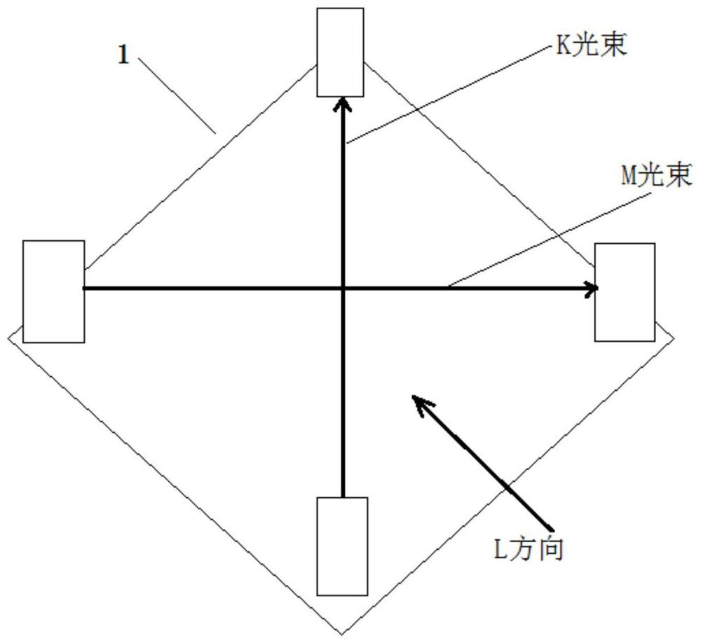
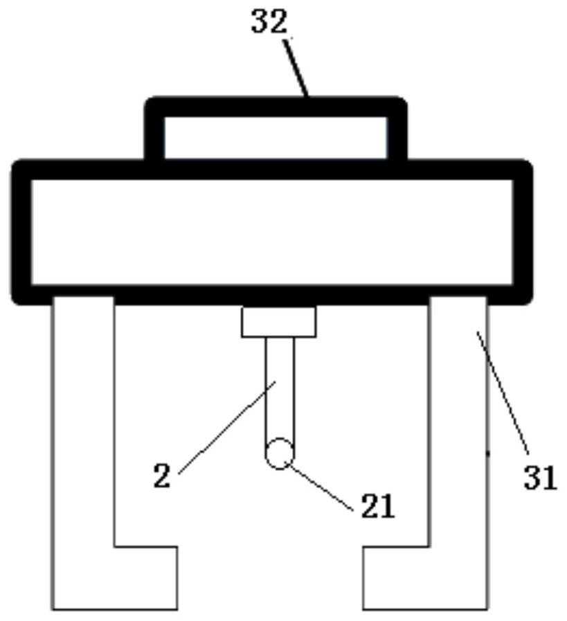
[0061] Robot slight collision compensation and correction system, which includes a standard laser detection unit 1 and a positioning pin 2;

[0062] The standard laser detection unit 1 is installed and fixed on the operation surface of the target product;

[0063] Such as figure 1 As shown, the standard laser detection unit 1 includes a K beam detection pair and an M beam detection pair;

[0064] The K-beam detection pair includes a K-beam transmitting end and a K-beam receiving end, and the K-beam emitting end emits a K-beam receiving end to the K-beam receiving end;

[0065] The M-beam detection pair includes an M-beam transmitting end and an M-beam receiving end, and the M-beam emitted from the M-beam transmitting end is directed to the M-beam receiving end;

[0066] The K beam emitting end, the K beam receiving end, the M beam emitting end, and the M beam receiving end are respectively located at the four endpoints of the rhombus;

[0067] The K beam intersects the M be...

Embodiment 2

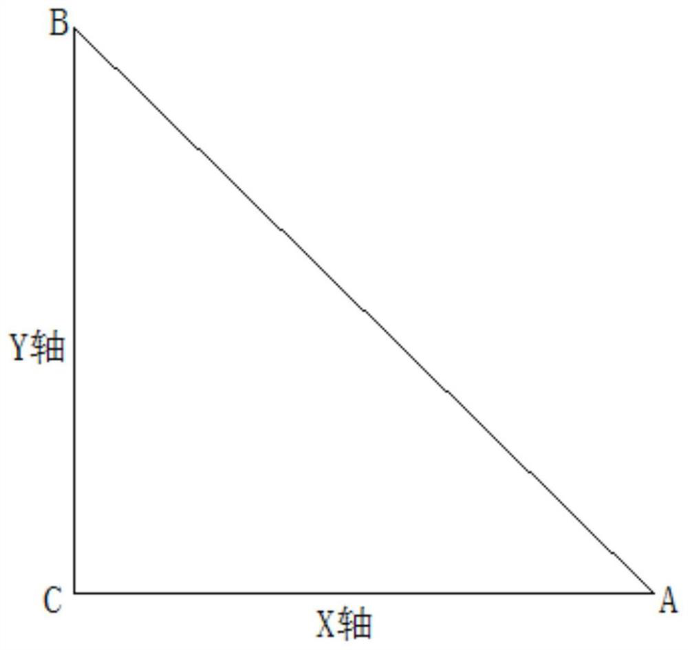
[0091] Based on the robot slight collision compensation and correction system of Embodiment 1, such as image 3 As shown, there are three standard laser detection units 1 installed and fixed on the operation surface of the target product;

[0092] The Z-axis coordinates of the geodetic coordinate system of the center points of the three standard laser detection units 1 are consistent;

[0093] The processor of the robot is calibrated with the earth coordinate system reference coordinates (a+X0, Y0, Z0) of the center point A of the first standard laser detection unit 1, and the earth coordinate system reference coordinates of the center point B of the second standard laser detection unit 1. Coordinates (X0, b+Y0, Z0), the geodetic coordinate system reference coordinates (X0, Y0, Z0) of the center point C of the third standard laser detection unit 1;

[0094] First, the robot detects the current coordinates of the geodetic coordinate system of the center point of three standard...

Embodiment 3

[0098] Based on the robot slight collision compensation and correction system of Embodiment 1, the tail end of the positioning pin 2 is fixed to the gripper side of the turntable with a buckle.

[0099] Preferably, the positioning pin 2 is coaxial with the turntable.

[0100] Preferably, the positioning pin 2 is made of steel.

[0101] Preferably, the jaws are steel cylinder jaws, which are not easily deformed mechanically.

[0102] Preferably, the standard laser detection unit is a standard laser detection unit from Captron.

[0103] In the third embodiment of the robot slight collision compensation and correction system, the installation of the positioning pin is snap-fit, avoiding the thread installation structure, because the thread installation structure itself is inclined.


PUM


Abstract

The invention discloses a robot slight collision compensation and correction system which comprises a standard laser detection unit and a positioning needle. The standard laser detection unit is installed and fixed on an operation surface of a target product. The standard laser detection unit comprises a K light beam transmitting end, a K light beam receiving end, an M light beam transmitting end and an M light beam receiving end; a robot clamping jaw is installed on a robot arm through a rotary disc; the tail end of the positioning needle is fixed on the clamping jaw side of the rotary disc; a probe ball is arranged at the head end of the positioning needle; a geodetic coordinate system reference coordinate (X0, Y0, Z0) of the central point of the standard laser detection unit is calibrated in a processor; the processor controls the clamping jaw to move, the current geodetic coordinate system coordinate value (x1, y1, z1) of the center point of the standard laser detection unit is obtained, and offset of the movement point position of the robot is corrected. According to the invention, offset of the motion point position of the robot caused by slight collision of the robot can be automatically, quickly and effectively corrected, and the working efficiency and the operation accuracy of the robot are improved.

Description

technical field [0001] The invention relates to industrial robot technology, in particular to a robot slight collision compensation and correction system. Background technique [0002] In today's automated production lines, robots are more and more widely used, which can not only reduce the manufacturing management costs of enterprises, but also improve manufacturing efficiency and reduce product manufacturing costs. [0003] However, robots have a common problem, that is, after the robot collides, the mechanical mechanism of the robot's gripper will shift, and it is necessary to manually teach the movement point to resume production. [0004] Manual teaching has the following problems: [0005] 1) It takes a long time. [0006] 2) The safety problem is obvious, and the safety switch needs to be shielded for teaching. [0007] 3) There are quality risks. If the process requirements cannot be fully matched after teaching, there will be batch quality risks. [0008] There...

Claims


Application Information

Patent Timeline
IPC IPC(8): G01B11/00
CPCG01B11/002
Inventor 李毓强张锐黄康姜银江
Owner UNITED AUTOMOTIVE ELECTRONICS SYST
Why Eureka
Try Eureka