
Industrial automatic remote intelligent control system

A technology of remote intelligent control and industrial automation, applied in general control systems, control/regulation systems, program control, etc., can solve the problems of inconvenient remote control and the inability to realize remote intelligent control of industrial automation, so as to reduce the failure rate and reduce Staffing, the effect of adding monitoring functions

Inactive Publication Date: 2021-04-30
合肥金人科技有限公司
View PDF6 Cites 3 Cited by
  • Summary
  • Abstract
  • Description
  • Claims
  • Application Information

AI Technical Summary

Problems solved by technology

[0002] At present, the application of remote intelligent control is more and more extensive. For example, the Chinese patent authorization announcement number is CN 211015086U, which discloses a remote intelligent control system for switches; including a signal unit, a central control unit, an intelligent control unit, a communication unit, a detection module, and a DTMF decoding module. , a drive module, and an industrial electrical unit, the output end of the central control unit communicates with the input end of the intelligent control unit, the intelligent control unit communicates with the drive module, the drive module communicates with the industrial electrical unit, and the Signal unit is one or more in telephone, network or APP, and the output end of described signal unit is respectively connected with the input end of detection module and the input end of DTMF decoding module, and the output end of described detection module and DTMF decoding The output ends of the modules are connected to the input end of the central control unit by communication. The central control unit and the communication unit are connected by two-way communication, which is intended to solve the problem that the existing intelligent industrial appliances are not convenient for remote control and have strong limitations. question;
[0003] However, it is only applied to interactive machines, and remote intelligent control of industrial automation cannot be realized

Method used


Image

  • Industrial automatic remote intelligent control system
  • Industrial automatic remote intelligent control system
  • Industrial automatic remote intelligent control system

Examples


Embodiment Construction

[0086] In order to make the purpose, technical solutions and advantages of the embodiments of the present invention clearer, the technical solutions in the embodiments of the present invention will be clearly and completely described below in conjunction with the embodiments of the present invention. Obviously, the described embodiments are part of the present invention Examples, not all examples. Based on the embodiments of the present invention, all other embodiments obtained by persons of ordinary skill in the art without creative efforts fall within the protection scope of the present invention.

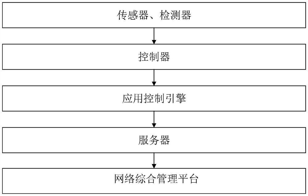
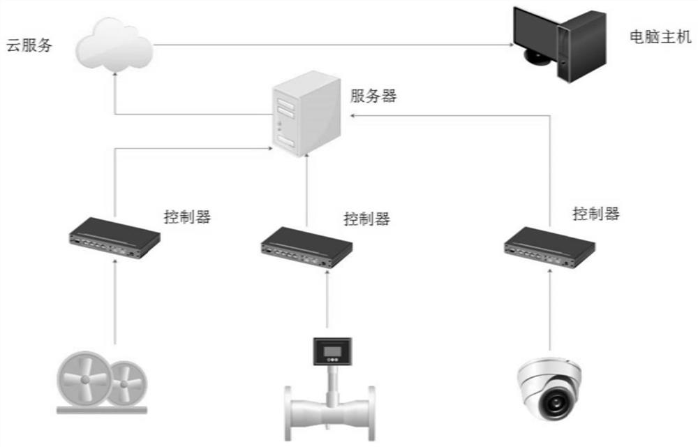
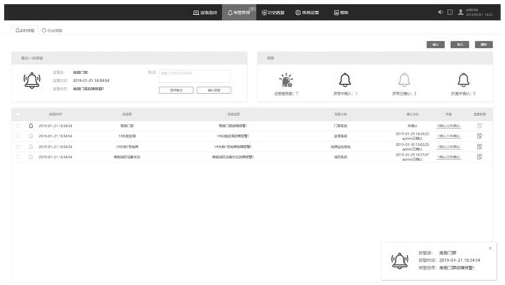
[0087] see figure 1 , an industrial automation remote intelligent control system, including a comprehensive network management platform, an equipment monitoring subsystem, an alarm management subsystem, a historical data subsystem, and an operation and maintenance management subsystem;

[0088] Please refer to Fig. tu 1 / tu 2, the integrated network management platform includes a...


PUM


Abstract

The invention discloses an industrial automation remote intelligent control system, which comprises an equipment monitoring subsystem used for collecting, detecting and outputting equipment monitoring data; an alarm management subsystem, used for receiving and processing alarm information; a historical data subsystem, used for classifying or summarizing and displaying historical data; an operation and maintenance management subsystem, used for routing inspection and maintenance management of the equipment; and a network comprehensive management platform which performs information interaction with the equipment monitoring subsystem, the alarm management subsystem and the operation and maintenance management subsystem and performs comprehensive analysis and management on the information. According to the invention, remote intelligent control of industrial automation is realized, personnel allocation is greatly reduced, and the production cost of enterprises is reduced; a monitoring function is added, and the failure rate of equipment is reduced; the industrial management and control efficiency is improved; the system is especially suitable for some dangerous and special environments and working conditions where people are inconvenient to go to field control and data acquisition.

Description

technical field [0001] The invention relates to the technical field of remote intelligent control, in particular to an industrial automation remote intelligent control system. Background technique [0002] At present, the application of remote intelligent control is more and more extensive. For example, the Chinese patent authorization announcement number is CN 211015086U, which discloses a remote intelligent control system for switches; including signal units, central control units, intelligent control units, communication units, detection modules, and DTMF decoding modules. , a drive module, and an industrial electrical unit, the output end of the central control unit communicates with the input end of the intelligent control unit, the intelligent control unit communicates with the drive module, the drive module communicates with the industrial electrical unit, and the Signal unit is one or more in telephone, network or APP, and the output end of described signal unit is r...

Claims


Application Information

Patent Timeline
IPC IPC(8): G05B19/418
CPCG05B19/41875G05B2219/32252Y02P90/02
Inventor 钟生胡增彭鹏
Owner 合肥金人科技有限公司
Learn More