Spin flash dryer

A rotary flash evaporation and drying machine technology, which is applied in the direction of mixers, evaporators, and mixers with rotary stirring devices, can solve the problems of difficult drying of materials, affecting the drying process, and easy agglomeration of materials, so as to improve the drying effect. Reduce material sticking to the wall, good drying effect

Active Publication Date: 2021-05-04
CHINA PETROLEUM & CHEM CORP +1
View PDF17 Cites 2 Cited by
  • Summary
  • Abstract
  • Description
  • Claims
  • Application Information

AI Technical Summary

Problems solved by technology

However, for materials with high viscosity and high moisture content, when spin flash drying is used, the material is easy to agglomerate when the spin flash is stirred and pulverized
If low temperature is used for drying, it is difficult to dry the agglomerated material, which will easily cause equipment blockage and make the drying process difficult; if high temperature drying is used, the material will be easily denatured
[0003] Chinese patent document CN206146147U provides a new type of energy-saving composite flash dryer for crushing and drying various powdery, filter cake, viscous and thinner materials. It uses efficient convective heat exchange drying to replace cyclone flash drying, and Through the indirect heat exchange method of the jacket sleeve, the material at the wall of the drum can be heated, which solves the problem that the scraper in the drum cannot effectively remove the material sticking to the wall of the drum, but it is not a real spin flash dryer. There is no product particle size classification function, and the drying effect is worse than spin flash drying
[0004] When drying materials with high viscosity and high moisture content, the materials will continue to dry during the falling process and the viscosity will continue to increase. The materials will first stick to the inner wall of the drying chamber and then stick to each other, resulting in a "bridge" phenomenon, and more and more aggregates , leading to blockage of the air flow channel in the drying chamber, which will affect the drying process in severe cases

Method used


Image

  • Spin flash dryer

Examples


Embodiment Construction

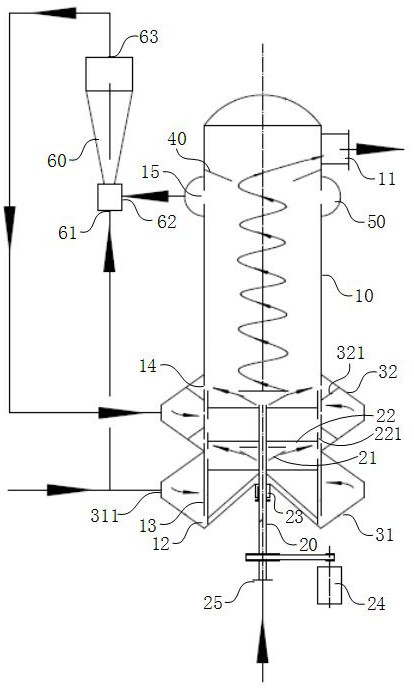
[0029] The specific embodiments of the present invention will be described in detail below in conjunction with the accompanying drawings, but it should be understood that the protection scope of the present invention is not limited by the specific embodiments.

[0030] Unless expressly stated otherwise, throughout the specification and claims, the term "comprise" or variations thereof such as "includes" or "includes" and the like will be understood to include the stated elements or constituents, and not Other elements or other components are not excluded.

[0031] In this document, for the convenience of description, spatially relative terms, such as "below", "below", "lower", "above", "above", "upper", etc., may be used to describe the relationship between one element or feature and another. The relationship of elements or features in the drawings. It will be understood that the spatially relative terms are intended to encompass different orientations of the item in use or o...


PUM


Abstract

The invention discloses a spin flash dryer, which comprises a cylinder body which is of a cylindrical structure, wherein the cylinder body sequentially comprises a rotary drying section, an impact drying section and a grading section from bottom to top, a product outlet is formed in the upper portion of the cylinder body, and an air inlet is formed in the lower portion of the cylinder body; a classifier arranged in the cylinder body and is lower than the product outlet; a rotating shaft coaxially penetrating through the bottom of the cylinder body, wherein the rotating shaft is a hollow shaft, and materials enter the cylinder body through the rotating shaft; at least a disperser, wherein the dispersers are coaxially communicated with the outside of the rotating shaft and are used for dispersing materials; at least one layer of stirring paddle coaxially connected outside the rotating shaft; and a gas distributor arranged at the lower part of the barrel in a surrounding manner, wherein the outer side of the gas distributor is communicated with hot air, and the inner side of the gas distributor is communicated with the gas inlet of the barrel. The spin flash dryer can treat materials with large viscosity and high moisture content, and is good in drying effect and stable in operation.

Description

technical field [0001] The invention relates to the technical field of drying equipment, in particular to a spin flash dryer. Background technique [0002] The spin flash dryer is a vertical fluidized bed dryer with a crushing device. It is a high-efficiency and fast combined dryer that can complete the crushing and drying of paste-like materials at one time. The hot air enters the crushing chamber from the annular gap at the bottom of the dryer. After being crushed, the contact surface area of ​​the material increases with the hot air. While being dried, it is further granulated by mechanical impact, centrifugal shearing, and frictional crushing. The qualified products are rotating Entrained by the airflow, it is discharged from the upper part of the dryer. However, for materials with high viscosity and high moisture content, when spin flash drying is used, the material is easy to agglomerate when the spin flash is stirred and pulverized. If low temperature is used for dr...

Claims


Application Information

Patent Timeline
Patent Type & Authority Applications(China)
IPC IPC(8): B01D1/18B01D1/14B01D1/30B01F5/04B01F7/18
CPCB01D1/18B01D1/14B01D1/30B01F25/312B01F27/90
Inventor 赵利民王晶晶金平王海波
Owner CHINA PETROLEUM & CHEM CORP
Why Eureka
Try Eureka