Method for judging position relation between shield tail and duct piece of large-diameter shield

A shield shield and large diameter technology is applied in the field of determining the positional relationship between the shield tail and the segment, which can solve problems such as affecting the construction progress, segment misplacement, damage, etc. The effect of reducing construction costs

Active Publication Date: 2021-05-04
ROAD & BRIDGE INT +1
View PDF8 Cites 0 Cited by
  • Summary
  • Abstract
  • Description
  • Claims
  • Application Information

AI Technical Summary

Problems solved by technology

[0003] With the continuous development of urban rail transit, the excavation diameter of the shield machine is also increasing, and the number of partitions of the propulsion cylinder of the shield machine is increasing. As a result, the position of the stroke sensor of the propulsion cylinder of each partition does not correspond to the stroke sensor of the hinged cylinder, resulting in the segment selection. Errors or even errors occurred in the judgment of the positional relationship between the segment and the shield tail, which eventually led to unreasonable selection of the segment, resulting in misalignment and damage of the segment during the excavation process, and even failure to assemble the segment due to the small gap between the shield tail
According to the corresponding normative requirements of urban rail transit, it is necessary to analyze the cause of the wrong platform and the segment with too large damaged area and shut it down, which greatly increases the construction cost and seriously affects the construction progress

Method used


Image

  • Method for judging position relation between shield tail and duct piece of large-diameter shield
  • Method for judging position relation between shield tail and duct piece of large-diameter shield
  • Method for judging position relation between shield tail and duct piece of large-diameter shield

Examples


Embodiment Construction

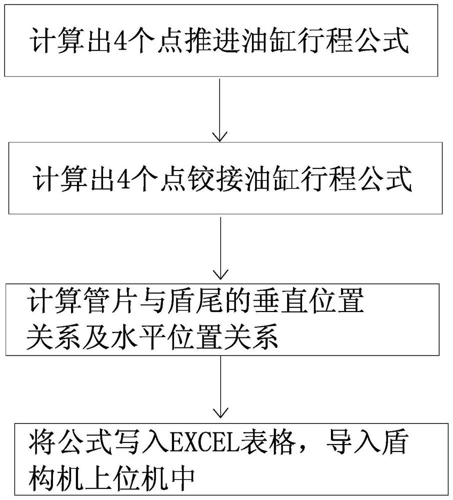
[0024] The overall process of the present invention is as figure 1 As shown, in the early stage of construction, according to the design drawings of the shield machine manufacturer, the calculation formulas of the propulsion cylinder stroke and hinge stroke of the selected four points are calculated through the spatial geometric relationship, and the formulas are input into the EXCEL table and then imported into the upper computer of the shield machine. After the import is completed, it can be used in the construction process.

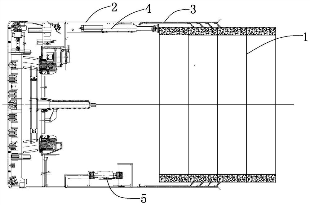
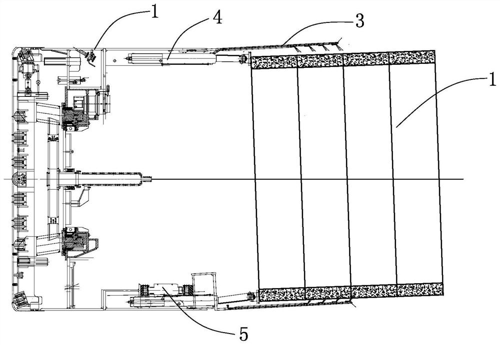
[0025] Such as figure 2 As shown, during the shield construction process, the center of the segment 1 coincides with the center of the front shield 2 in the shield machine, and the space between the segment 1 and the shield tail 3 is geometrically parallel, which is the optimal positional relationship between the segment and the shield tail. However, in the actual construction process, because the shield machine needs to fit the design axis for excav...


PUM


Abstract

The invention provides a method for judging the position relation between a shield tail and a duct piece of a large-diameter shield. The method comprises the following steps of in the early stage of construction, according to a design drawing of a shield machine manufacturer, calculating calculation formulas of thrust oil cylinder strokes and hinging oil cylinder strokes of four selected points through a space geometrical relation; further calculating a vertical position relation formula of the duct piece and the shield tail according to the calculation formulas of the thrust oil cylinder strokes and hinging oil cylinder strokes; and establishing an EXCEL table, inputting the thrust oil cylinder strokes, the hinging oil cylinder strokes, the calculation formulas of the thrust oil cylinder strokes and the hinging oil cylinder strokes of the corresponding point and the position relation judgment formula of the duct piece and the shield tail of each subarea into the table, and then importing into an upper computer of the shield tunneling machine so that the position relation between the shield tail and the duct piece can be judged. According to the method, the judgment basis of duct piece type selection is optimized, and the tunnel forming quality and the construction efficiency can be improved.

Description

technical field [0001] The invention belongs to the technical field of tunnel construction, and in particular relates to a method for determining the positional relationship between a shield tail and a segment when a shield tunneling method is used for subway tunnel construction. Background technique [0002] Segment selection for shield tunneling is an important link in the construction of shield-tunneled subway tunnels. The quality of segment selection directly affects the posture adjustment of shield tunneling and the assembly quality of segments. The existing segment selection method is mainly based on the following data: (1) stroke difference of propulsion cylinder in each zone of shield machine; (2) shield tail clearance; (3) attitude of shield machine; (4) stroke of hinged cylinder in each zone Difference. Through the comparison of the above data, determine the segment trend, posture, position relationship with the shield tail, and fit with the trend of the shield ma...

Claims


Application Information

Patent Timeline
Patent Type & Authority Applications(China)
IPC IPC(8): E21D11/08E21D9/06
CPCE21D11/08E21D9/0607
Inventor 彭鑫
Owner ROAD & BRIDGE INT
Why Eureka
Try Eureka