Roller kiln broken roller detection system and method

A detection system, roller kiln technology, applied in the direction of furnace type, furnace, lighting and heating equipment, etc., can solve the problems of low degree of automation and intelligence, inability to detect roller bars, high labor costs, etc., and achieve low wiring complexity, The effect of reducing the number of control points and making wiring difficult

Active Publication Date: 2021-05-04
HUNAN JINLU TECH CO LTD
View PDF10 Cites 0 Cited by
  • Summary
  • Abstract
  • Description
  • Claims
  • Application Information

AI Technical Summary

Problems solved by technology

However, this partition detection scheme cannot accurately and timely detect each individual roller bar, and still requires manual assistance, which has a low degree of automation and intelligence and high labor costs.

Method used


Image

  • Roller kiln broken roller detection system and method
  • Roller kiln broken roller detection system and method

Examples


Embodiment 1

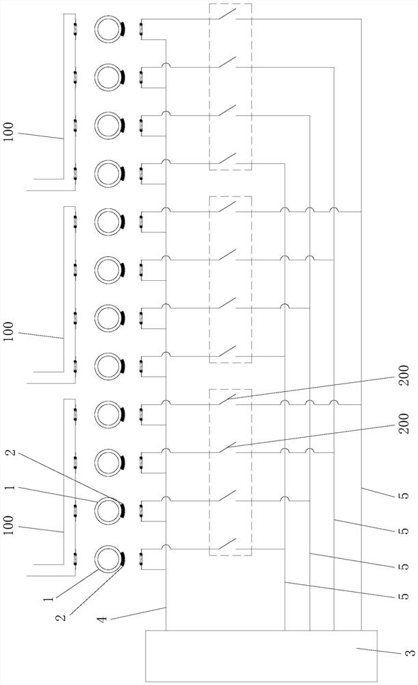
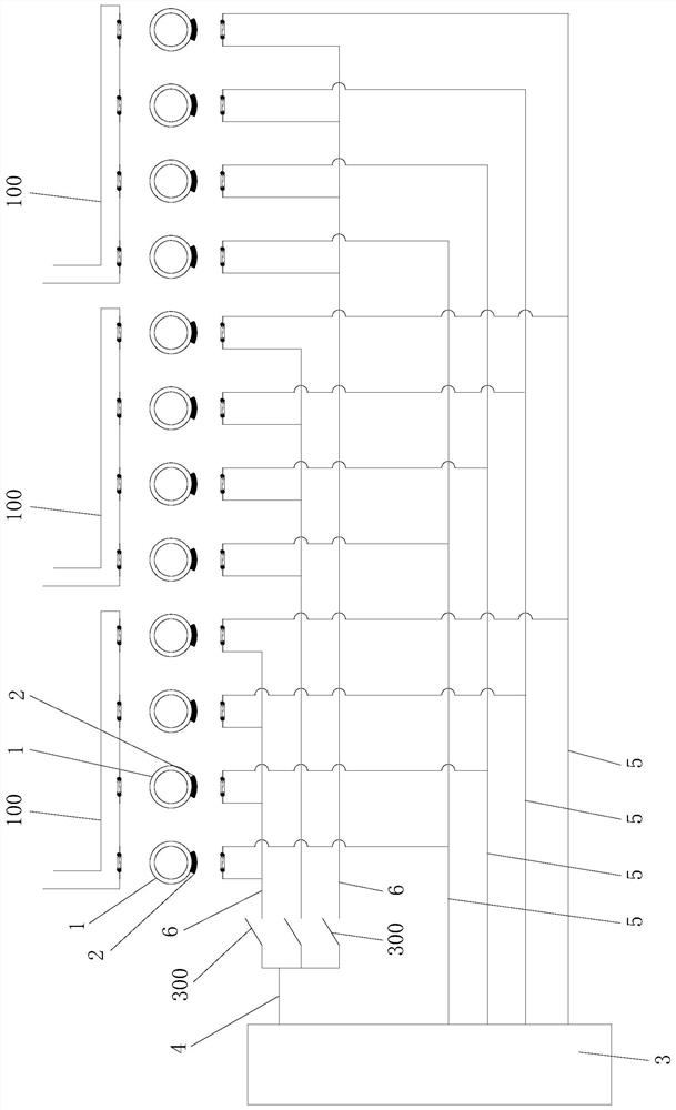
[0028] Such as figure 1 As shown, the roller kiln broken roll detection system of this embodiment includes a plurality of roller bars 1 installed in the roller kiln, and each roller bar 1 is provided with a detector 2 for detecting whether the roller bar 1 is broken, and each detection The detector 2 is connected to the detection control device 3, and the detection control device 3 is connected with a signal transmitting line 4 and a plurality of signal receiving lines 5, and the plurality of roller bars 1 are divided into more than two groups of rod groups, and the number of each rod group includes no more than the number of signal receiving rods. There are 5 rollers 1, and the detector 2 of each roller 1 in each group of rods is connected to the signal transmitting line 4 and an independent signal receiving line 5, that is, the detection of each roller 1 in each group of rods The detector 2 is connected to one of the plurality of signal receiving lines 5 mentioned above, and...

Embodiment 2

[0036] A detection method of a roller kiln broken roll detection system in embodiment 1, comprising the following steps:

[0037] (S1) The detection control device 3 adopts synchronous detection of multiple series detection loops 100;

[0038] (S2) Enter step (S3) when it is detected that any one of the series detection circuits 100 has a broken roll bar 1, and return to step (S1) when it is detected that no roll bar 1 is broken in all series detection circuits 100;

[0039] (S3) Make all the detectors 2 in the series detection circuit 100 with the roller bar 1 broken and the detection control device 3 connected through the on-off control assembly, and the detectors 2 in the remaining series detection circuits 100 are disconnected from the detection control device 3 On, so that the detection control device 3 performs synchronous detection on all the detectors 2 in the series detection circuit 100 with a broken roll bar 1 and judges whether each broken roll bar 1 is broken.

...


PUM


Abstract

The invention relates to a roller kiln broken roller detection system and method. The detection system comprises a plurality of roller bars provided with detectors, a detection control device is connected with a signal emission line and a plurality of signal receiving lines, the multiple roller bars are divided into two or more bar groups, and the detector of each roller bar in each bar group is connected with the signal emission line and one independent signal receiving line. Each bar group is correspondingly provided with an on-off control assembly, all detectors in each bar group are connected in series to form an independent series detection loop, wherein the series detection loop is connected with the detection control device, and the roller kiln broken roller detection system is low in wiring complexity and wiring difficulty, simple and convenient to assemble and maintain, easy to control, low in cost and high in detection efficiency. According to the detection method, synchronous detection is carried out on the multiple series detection loops, when it is detected that a roller bar in any series detection loop is broken, synchronous detection is carried out on all the detectors in the series detection loop with the broken roller bar, the roller bar breaking condition of each roller bar can be accurately detected, control is easy and convenient, and the detection efficiency is high.

Description

technical field [0001] The invention relates to the technical field of heat treatment kilns, in particular to a roller kiln broken roller detection system and detection method. Background technique [0002] Roller kiln, also known as roller hearth kiln, is a continuous firing tunnel kiln using rotating refractory rollers as a vehicle. Products (materials) are placed on multiple horizontally spaced rollers, driven by the rotation of the rollers. The product passes through the hearth of the roller kiln to complete sintering. In the actual operation of the roller kiln, the roller may be broken. At this time, the roller rods need to be replaced in time, otherwise the transmission system will not run smoothly, and even continuous roller breakage will occur. In severe cases, it will lead to accidents in the arch kiln. Therefore, roller kilns are generally equipped with a roller breakage detection system. [0003] At present, there are mainly two schemes for the detection and ide...

Claims


Application Information

Patent Timeline
Patent Type & Authority Applications(China)
IPC IPC(8): F27B9/40F27B9/24
CPCF27B9/40F27B9/2407
Inventor 欧阳建张勋郎唐植蕾
Owner HUNAN JINLU TECH CO LTD
Why Eureka
Try Eureka