Centralized heating flue gas desulfurization and denitrification treatment system and method thereof

A technology of desulfurization and denitrification and treatment system, which is applied in the flue gas desulfurization and denitrification treatment system with centralized heating, in the field of flue gas desulfurization and denitrification, and can solve the problems of consuming more fuel and polluting the air

Active Publication Date: 2021-02-26
ZHONGYE-CHANGTIAN INT ENG CO LTD
View PDF10 Cites 0 Cited by
  • Summary
  • Abstract
  • Description
  • Claims
  • Application Information

AI Technical Summary

Problems solved by technology

The hot blast stove itself produces a certain amount of flue gas. Since the hot blast stove is burning, the flue gas produced contains pollutants such as nitrogen dioxide and nitrogen monoxide; in the prior art, the gas generated by the hot blast stove is directly discharged, polluting the air
At the same time, the hot blast stove uses air at normal temperature as the combustion-supporting gas, and heating this part of the combustion-supporting gas to the temperature required by the heat exchange medium (generally 400-460°C) requires a large amount of fuel; that is to say, part of the fuel in the hot blast stove needs to be used It is used to heat the combustion-supporting gas, resulting in the need to consume more fuel and produce a larger amount of pollutant-containing flue gas

Method used


Image

  • Centralized heating flue gas desulfurization and denitrification treatment system and method thereof
  • Centralized heating flue gas desulfurization and denitrification treatment system and method thereof

Examples


Embodiment 1

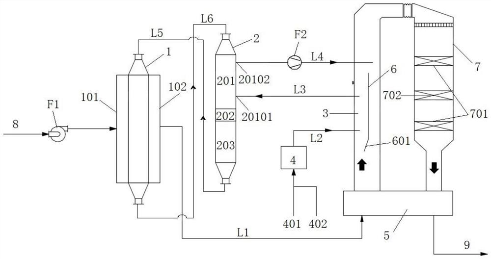
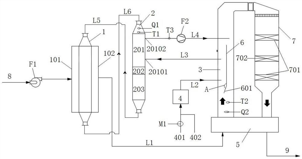
[0111] Such as figure 1 As shown, a centralized heating flue gas desulfurization and denitrification treatment system includes an activated carbon adsorption tower 1, an activated carbon desorption tower 2, a hot blast stove 4 and an SCR reactor 7. According to the direction of flue gas, one side of the activated carbon adsorption tower 1 is provided with a raw flue gas inlet 101 , and the other side is provided with a desulfurized flue gas outlet 102 . The desulfurized flue gas outlet 102 is connected to the SCR reactor 7 through the first pipeline L1. The clean flue gas discharged from the SCR reactor 7 is discharged through the gas outlet of the SCR reactor 7 . A deflector 6 is arranged in the first pipeline L1. The cavity formed between the deflector 6 and the side wall of the first pipe L1 forms the air mixing chamber 3 , and the air outlet of the hot stove 4 communicates with the air mixing chamber 3 through the second pipe L2 .

[0112] Wherein, the activated carbon ...

Embodiment 2

[0114] Embodiment 1 is repeated, except that the lower end of the deflector 6 is provided with a movable plate 601 . The size of the air inlet of the air mixing chamber 3 is regulated by controlling the opening and closing degree of the movable plate 601 .

Embodiment 3

[0116] Example 2 was repeated, except that the system also included a GGH heat exchanger 5 . The gas outlet from the SCR reactor 7 is connected with an exhaust pipe 9 . The GGH heat exchanger 5 is connected to the first pipeline L1 and the exhaust pipeline 9 respectively. The flue gas desulfurized by the activated carbon adsorption tower 1 is sent to the air inlet of the SCR reactor 7 after heat exchange by the GGH heat exchanger 5 . The clean flue gas discharged from the SCR reactor 7 is discharged through the exhaust pipe 9 after being heat-exchanged by the GGH heat exchanger 5 . The communication position between the second pipeline L2 and the air mixing chamber 3 is located downstream of the connection position between the GGH heat exchanger 5 and the first pipeline L1.


PUM

PropertyMeasurementUnit
heightaaaaaaaaaa
heightaaaaaaaaaa

Abstract

The invention discloses a centralized heating flue gas desulfurization and denitrification treatment system and a method thereof. The centralized heating flue gas desulfurization and denitrification treatment system comprises an activated carbon adsorption tower, an activated carbon desorption tower, a hot blast stove and an SCR reactor, a flow guide plate is arranged in a flue gas pipeline, a cavity formed between the flow guide plate and the side wall of the flue gas pipeline forms an air mixing chamber, hot air generated by fuel combustion of the hot blast stove is introduced into the air mixing chamber to be evenly mixed with part of desulfurized flue gas to form a heat medium, and the part of the heat medium is used for realizing activated carbon thermal regeneration of the heating section of the activated carbon desorption tower and heating flue gas to be denitrified of the SCR system. The system and method are low in investment cost, simple in structure, high in adaptability andpracticability, high in control precision and obvious in flue gas desulfurization and denitrification effect.

Description

technical field [0001] The invention relates to flue gas desulfurization and denitrification technology, in particular to a centralized heating flue gas desulfurization and denitrification treatment system and method, belonging to the technical field of flue gas purification. Background technique [0002] For industrial flue gas, especially for sintering machine flue gas in the iron and steel industry, flue gas desulfurization and denitrification technology is a flue gas purification technology applied to the chemical industry where multiple nitrogen oxides and sulfur oxides are generated. Nitrogen oxides and sulfur oxides are one of the main sources of air pollution. Most of flue gas simultaneous desulfurization and denitrification technologies are currently in the research and industrial demonstration stage, but because it can simultaneously achieve desulfurization and denitrification in one system, especially with the X Control standards are becoming increasingly stringe...

Claims


Application Information

Patent Timeline
Patent Type & Authority Applications(China)
IPC IPC(8): B01D53/02B01D53/04B01D53/86B01D53/56F23J15/08
CPCB01D53/02B01D53/0454B01D53/8628B01D53/8631B01D53/56F23J15/08B01D2253/102B01D2259/4009B01D2258/0283Y02A50/20
Inventor 魏进超康建刚李小龙徐忠
Owner ZHONGYE-CHANGTIAN INT ENG CO LTD
Why Eureka
Try Eureka