
Method and device for chopper braking control of multi-level frequency converter

A brake control and frequency converter technology, applied in the field of frequency converter control, can solve problems such as motor torque vibration, over-current fault, and adverse effects of frequency converter control performance

Active Publication Date: 2022-03-22
CHAJNA MAJNING DRAJVS EHND AUTOMEHJSHN KO
View PDF8 Cites 0 Cited by
  • Summary
  • Abstract
  • Description
  • Claims
  • Application Information

AI Technical Summary

Problems solved by technology

The above methods will cause the voltage imbalance of each sub-bus, which will have a negative impact on the control performance of the inverter, and in severe cases will cause motor torque vibration or over-current faults.

Method used


Image

  • Method and device for chopper braking control of multi-level frequency converter
  • Method and device for chopper braking control of multi-level frequency converter
  • Method and device for chopper braking control of multi-level frequency converter

Examples


Embodiment Construction

[0059]In order to deepen the knowledge and understanding of the present invention, the technical solutions of the present invention will be further introduced below in conjunction with the accompanying drawings and specific embodiments.

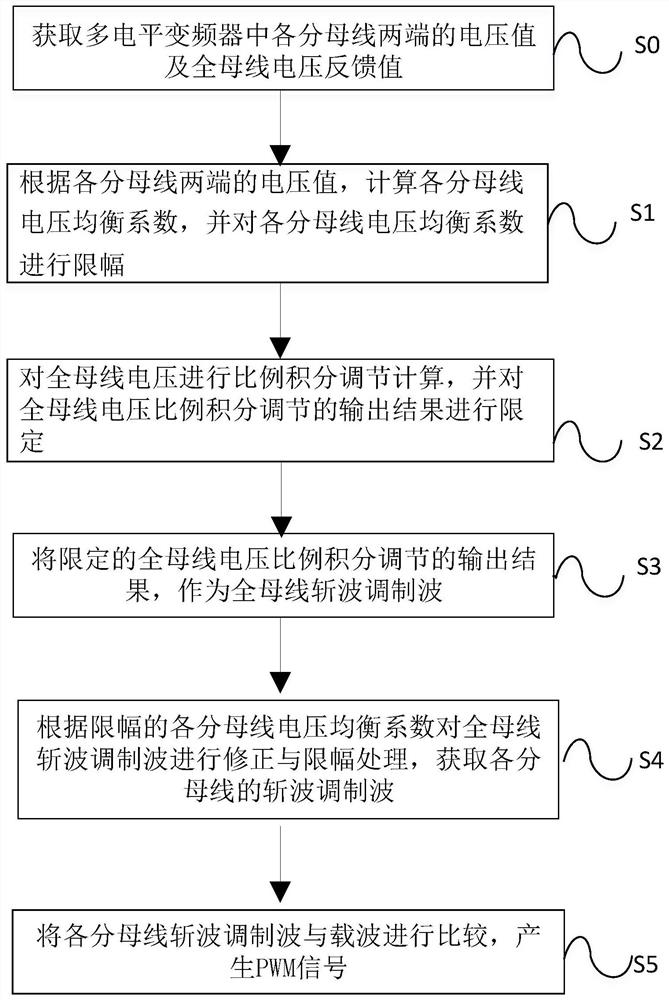
[0060] The embodiment of the present invention provides a multi-level frequency converter chopper braking control method, which can independently discharge each sub-bus of the multi-level, and solve the voltage balance control of each sub-bus at the same time during the discharge process. figure 1 A flow chart of a control method for chopper braking of a multi-level inverter provided by an embodiment of the present invention, the method includes the following steps:

[0061] Step S0: Obtain the voltage values ​​at both ends of each sub-bus in the multi-level inverter and the voltage feedback value of the whole bus.

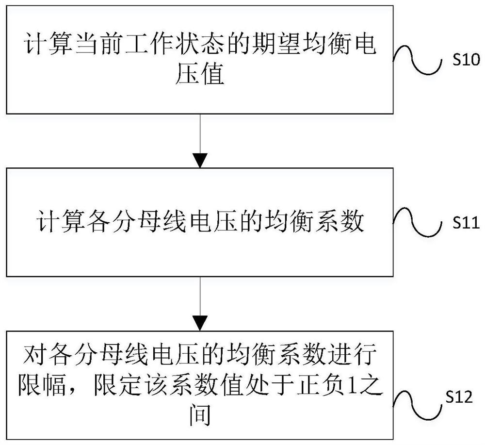
[0062] Step S1: Calculate the voltage equalization coefficient of each sub-bus according to the voltage values ​​at both ends o...


PUM


Abstract

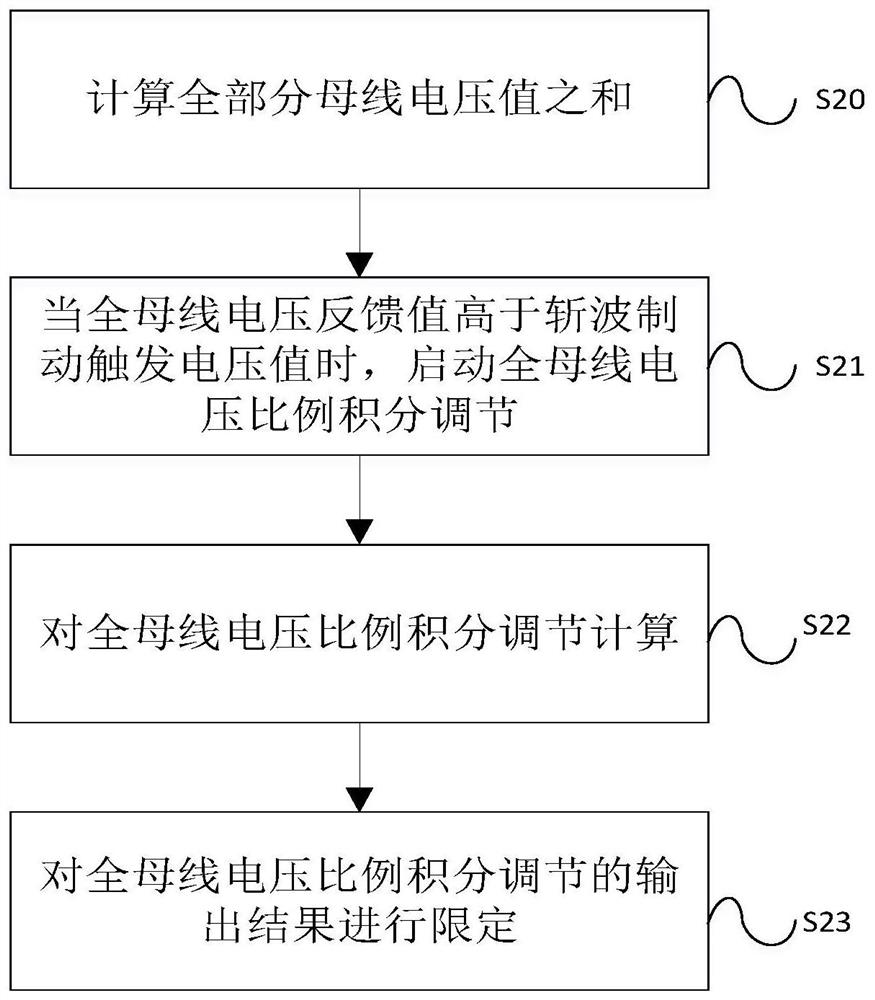
The invention discloses a chopper braking control method of a multi-level frequency converter. The method comprises: obtaining the voltage value at both ends of each sub-bus in the multi-level frequency converter and the voltage feedback value of the whole bus, and according to the voltage at both ends of each sub-bus value, calculate the equalization coefficient of each sub-bus voltage, and limit the equalization coefficient of each sub-bus voltage, carry out proportional-integral adjustment calculation on the full-bus voltage, and limit the output result of the full-bus voltage proportional-integral adjustment; according to the limiting Each sub-bus voltage equalization coefficient corrects and limits the chopping modulation wave of the whole bus to obtain the chopping modulation wave of each sub-bus; compares the chopping modulation wave of each sub-bus with the carrier to generate a PWM signal. The method solves the problem that the chopper braking circuit cannot be applied due to the limitation of the withstand voltage of the power semiconductor device in the high-voltage application occasion, and also realizes the dynamic balance of multiple denominator bus voltages during the discharge process.

Description

technical field [0001] The invention relates to the field of frequency converter control, in particular to a multilevel frequency converter chopper braking control method and device. Background technique [0002] As the capacity of the inverter continues to increase, the voltage level of the inverter continues to increase. The way to increase the output voltage through a multi-level topology is considered to be the best strategy for increasing the output voltage at present. The difficulty of this method is that each denominator bus voltage must be dynamically balanced, otherwise it will cause torque ripple of the motor. [0003] In the prior art, the entire DC bus of the frequency converter is chopped and discharged. This technical means adopts the method of series chopping of power semiconductor devices to realize the discharge of the high DC voltage bus. In the prior art, there is also a method of discharging multiple denominator buses of the frequency converter. The abo...

Claims


Application Information

Patent Timeline
Patent Type & Authority Patents(China)
IPC IPC(8): H02M7/483H02M7/5395H02P27/08
CPCH02M7/483H02M7/5395H02P27/08
Inventor 谭国俊杨波
Owner CHAJNA MAJNING DRAJVS EHND AUTOMEHJSHN KO
Learn More