Battery unit connection lines for energy storage systems used in high-power and high-voltage conditions

An energy storage system and battery unit technology, applied in the field of energy storage systems, can solve the problems of low balancing efficiency and high balancing management cost, and achieve the effects of small line loss, extended effective time, and high overall efficiency

Active Publication Date: 2018-05-29
NAT ENG RES CENT OF ADVANCED ENERGY STORAGE MATERIALS SHEN ZHEN LTD CO
View PDF6 Cites 0 Cited by
  • Summary
  • Abstract
  • Description
  • Claims
  • Application Information

AI Technical Summary

Problems solved by technology

If there is no better solution to achieve the dynamic consistency of the energy storage system during use, the energy storage system often needs to operate with limited capacity or limited power, which cannot well meet the needs of actual working conditions
[0004] In order to solve this problem, a balance management module is generally set in the BMS (battery management system). The commonly used balance method is to add a hardware structure circuit in the BMS (battery management system) as a balance management module. When the system is running, turn on the balance mode to consume the excess power in the high-voltage or high-SOC single battery in the system, and adjust the voltage and charge of the single battery to the target level set by the system to achieve the purpose of balance. However, this method has the problems of high equilibrium management cost and low equilibrium efficiency.

Method used


Image

  • Battery unit connection lines for energy storage systems used in high-power and high-voltage conditions
  • Battery unit connection lines for energy storage systems used in high-power and high-voltage conditions
  • Battery unit connection lines for energy storage systems used in high-power and high-voltage conditions

Examples


Embodiment 1

[0020] The present invention will be described in further detail below in conjunction with the accompanying drawings and embodiments. This embodiment uses a nickel metal hydride D-type 1.2V6Ah battery and an energy storage system composed of this type of single battery for illustration. The energy storage system is composed of 3360 single batteries. The rated voltage of the energy storage system is 576V and the rated energy is 24.2kWh.

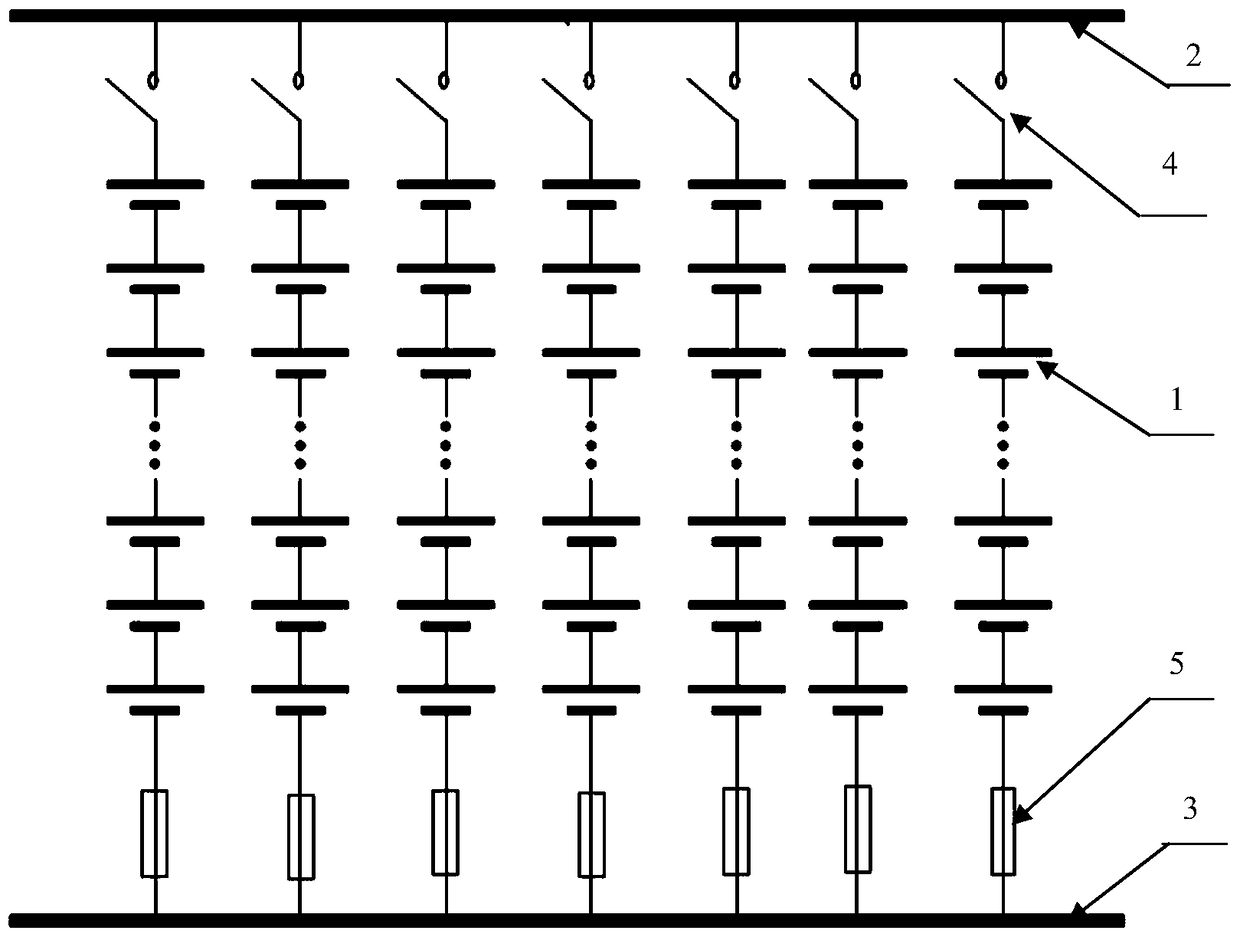
[0021] figure 1 The combined structural form of the energy storage system of the comparative example is shown. First, 480 single cells 1 are connected in series to form a column, and a relay 4 is provided at the place where the positive pole of each column is connected to the total positive 2, and a fuse 5 is provided at the place where the negative pole of each column is connected to the total negative 3. Then the same 7 columns of negative poles are connected in parallel to the total negative 3, and the 7 columns of positive poles are conn...


PUM


Abstract

The present invention provides a battery unit connection circuit for an energy storage system applied to high-power and high-voltage working conditions. Firstly, the single batteries are connected in series to form a main circuit, and multiple main circuits are connected in parallel, and then each row of cells on the main circuit is The batteries are connected in parallel to form a secondary circuit. The main circuit is responsible for the path of electric energy exchange with the outside. The connection resistance between the circuit units is in a certain ratio, and fuses are set on the main circuit and the secondary circuit. The present invention enables the energy storage system to exhibit higher energy efficiency through the setting of the primary and secondary circuits, which is a good combination of energy storage system balance and normal operation, realizes dynamic balance between parallel battery units, and enhances consistency under working conditions , which can prolong the effective time of high-power operation of the energy storage system.

Description

technical field [0001] The invention relates to an energy storage system, in particular to a composition structure of an energy storage system, a battery unit connection circuit and a unit monitoring and management method for high-power and high-voltage applications. Background technique [0002] With the advancement of battery energy storage system technology, the specific energy of its energy storage has increased rapidly, and the unit cost has gradually decreased. In addition, the battery energy storage system itself has the characteristics of fast response and convenient setting, making the application of battery energy storage system in It is also becoming more and more common in high-power and high-voltage working conditions. [0003] Normally, a battery energy storage system is composed of a large number of single batteries connected in series and parallel to form a complete system to realize the storage and release of electric energy of a certain scale. In occasions...

Claims


Application Information

Patent Timeline
Patent Type & Authority Patents(China)
IPC IPC(8): H02J7/00H02H7/18
Inventor 刘宏兵陈晓峰钟发平胡顺华卓亨黄兰妮徐佳英
Owner NAT ENG RES CENT OF ADVANCED ENERGY STORAGE MATERIALS SHEN ZHEN LTD CO
Why Eureka
Try Eureka