Humidifying device for ventilator

A ventilator and humidification technology, applied in the direction of respirators, medical devices, and other medical devices, can solve problems such as poor gas flow, manual cleaning and recycling of liquid collection bottles, and the lack of automatic water addition in humidification tanks. , to achieve the effect of reducing workload and smooth gas flow

Pending Publication Date: 2021-05-07
LIUZHOU PEOPLES HOSPITAL
View PDF0 Cites 1 Cited by
  • Summary
  • Abstract
  • Description
  • Claims
  • Application Information

AI Technical Summary

Problems solved by technology

[0003] In view of the above, it is necessary to provide a humidification device for a ventilator, which is used to solve the problem that the humidification tank does not have the function of automatically adding water, the problem that the air supply pipe and the air outlet pipe are easy to cause poor gas flow due to severe atomization, and the integrated Liquid bottles need to be manually cleaned to recycle water

Method used


Image

  • Humidifying device for ventilator
  • Humidifying device for ventilator
  • Humidifying device for ventilator

Examples


Embodiment 1

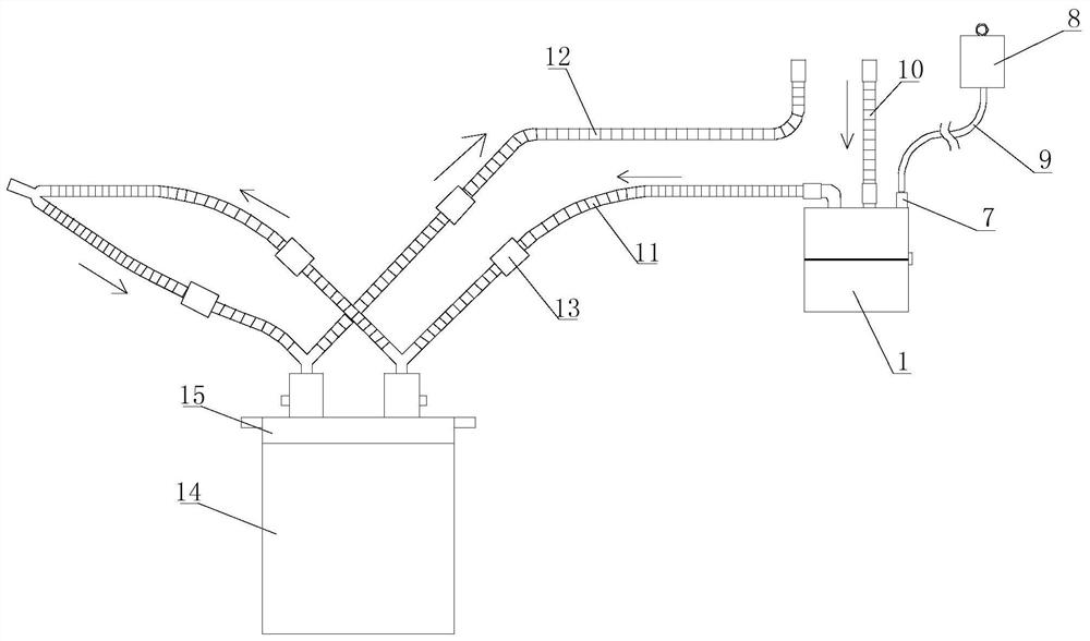
[0039] Such as Figure 1-3 As shown, a humidification device for a ventilator includes a humidification tank 1, an infusion device, an air inlet pipe 10, an air supply pipe 11, an air outlet pipe 12, a liquid collection bucket and a control box.

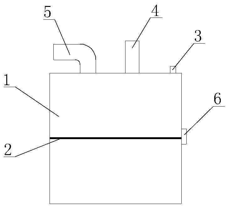
[0040] The outside of the humidification tank 1 is provided with a water level line 2 , and the humidification tank 1 is provided with a first liquid level sensor 6 , and the sensing point of the first liquid level sensor 6 is at the same height as the water level line 2 . The top of the humidification tank 1 is provided with a water inlet 3 , an air inlet 4 and a humidification gas outlet 5 , and the water inlet 3 is provided with a first solenoid valve 7 . The lower part of the water filling port 3 is connected with a water adding conduit, and the water adding conduit extends to the lower part of the inner cavity of the humidification tank 1 .

[0041] The infusion device includes an infusion container 8 and an infusion tube 9, th...

Embodiment 2

[0049] Such as Figure 4-5 As shown, on the basis of Embodiment 1, the humidified gas outlet 5 is provided with a monitoring joint 25 and is connected to the gas delivery pipe 11 through the monitoring joint 25 . A gas flow sensor 26 is disposed in the monitoring joint 25 , and the gas flow sensor 26 is electrically connected to the controller 24 . The controller 24 monitors the gas flow rate in the gas delivery pipe 11 through the gas flow sensor 26, and when the gas flow rate is lower than a set value, the controller 24 controls the vibrator 13 to work. The gas flow sensor 26 is used to monitor the gas flow rate in the gas delivery tube 11; when the gas flow rate is lower than the set value, it indicates that the atomization in the gas delivery tube 11 is relatively serious, and the water mist generated when the patient exhales is attached to the gas delivery tube 11 and the outlet tube 11. The inner wall of the trachea 12 hinders the gas flow in the air supply pipe 11 and ...


PUM


Abstract

The invention discloses a humidifying device for a ventilator, which belongs to the technical field of humidifying devices and comprises a humidifying tank, a liquid conveying device, an air inlet pipe, an air supply pipe, an air outlet pipe, a liquid collecting barrel and a control box; the humidifying tank is provided with a water level line, a first liquid level sensor, a water adding opening, an air inlet and a humidified air outlet; the water adding opening is provided with a first electromagnetic valve, the liquid conveying device is connected with the first electromagnetic valve, and vibrators are detachably installed on the air supply pipe and the air outlet pipe; a first liquid collecting bottle and a second liquid collecting bottle are arranged on the top surface of the liquid collecting barrel; the first liquid collecting bottle is connected with the middle of the air supply pipe and has an automatic liquid discharging function; the second liquid collecting bottle is connected with the middle part of the air outlet pipe and has an automatic liquid discharging function; and the control box comprises a box body and a controller arranged in the box body. The humidifying device for the ventilator solves the problems that the humidifying tank does not have an automatic water adding function, the air supply pipe and the air outlet pipe are prone to being seriously atomized to cause unsmooth air flowing, and recycled water in the liquid collecting bottle needs to be manually cleaned.

Description

technical field [0001] The invention relates to the technical field of humidification devices, in particular to a humidification device for a ventilator. Background technique [0002] At present, critically ill patients in the intensive care unit need to use a ventilator to assist breathing. There is a humidification tank on the ventilator, which contains sterilized water, and the water volume is required. The water level must be near the standard line, not too much or too little; The humidification tank does not have the functions of water level monitoring and automatic water filling. The clinical work is relatively busy, and the medical staff cannot always pay attention to the water level of the humidification tank; therefore, in actual work, the water level in the humidification tank is often lower than the standard line; In addition, the humidification tank is connected with an air supply pipe, and the end of the air supply pipe away from the humidification tank is conne...

Claims


Application Information

Patent Timeline
Patent Type & Authority Applications(China)
IPC IPC(8): A61M16/16
CPCA61M16/162A61M2205/3386A61M16/161A61M16/164
Inventor 郭晖晖樊蕙高星何灵韦玲丹
Owner LIUZHOU PEOPLES HOSPITAL
Why Eureka
Try Eureka