Sizing die set and finishing machine with same

A shaping mold and mold base technology, which is applied in metal processing equipment, feeding devices, forming tools, etc., can solve the problems of low production efficiency of automatic shaping machines, product quality that cannot fully meet the requirements, and difficult product tolerance adjustment.

Pending Publication Date: 2021-05-07
SHANXI XINHUAN POWDER METALLURGY
View PDF0 Cites 0 Cited by
  • Summary
  • Abstract
  • Description
  • Claims
  • Application Information

AI Technical Summary

Problems solved by technology

However, the parallelism of the products currently produced should be within 0.02mm, and the flatness should be within 0.01mm.
Difficult to adjust product tolerances to median values
As a result, the quality of the product cannot fully meet the requirements, and the accuracy of most punching machines is above 2 wires. The existing technology cannot fully meet the technical requirements on the drawings, and there are mainly the following defects:
[0004] 2. The efficiency of plastic mold replacement is too low, an average of 1 to 4 hours
[0005] 3. The production efficiency of conventional automatic shaping machine is low, 2000 / shift
[0006] 4. Artificial plastic surgery has potential safety hazards

Method used


Image

  • Sizing die set and finishing machine with same
  • Sizing die set and finishing machine with same
  • Sizing die set and finishing machine with same

Examples


Embodiment Construction

[0041] The following clearly and completely describes the technical solutions in the embodiments of the present invention. Obviously, the described embodiments are only some of the embodiments of the present invention, but not all of them. Based on the embodiments of the present invention, all other embodiments obtained by persons of ordinary skill in the art without making creative efforts belong to the protection scope of the present invention.

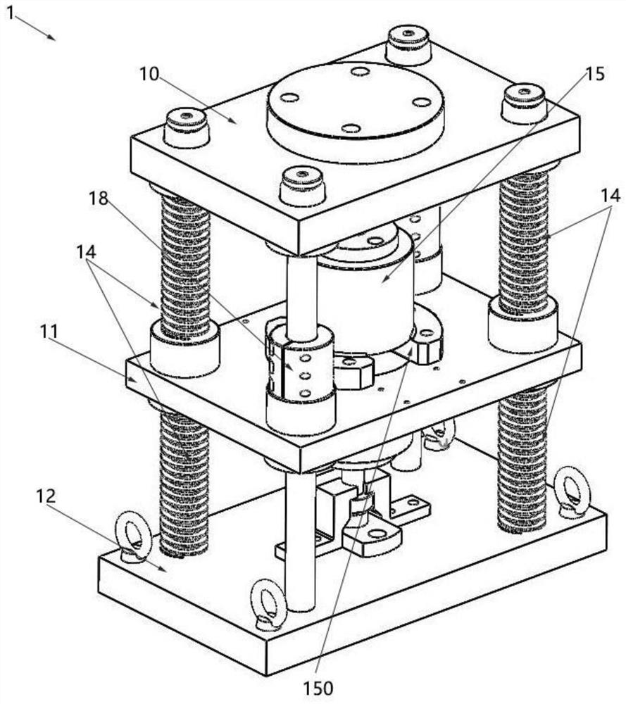
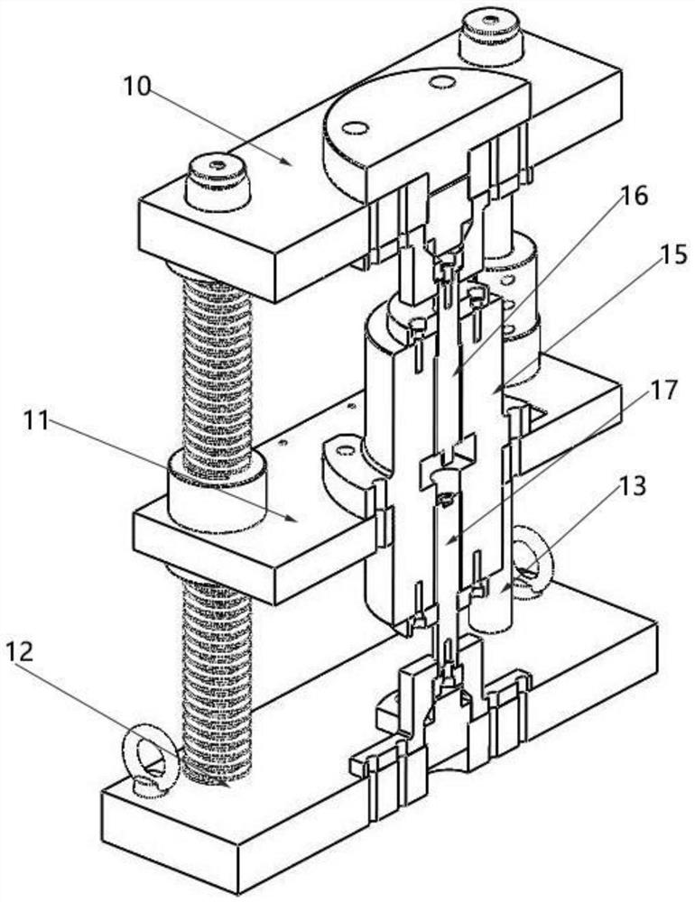
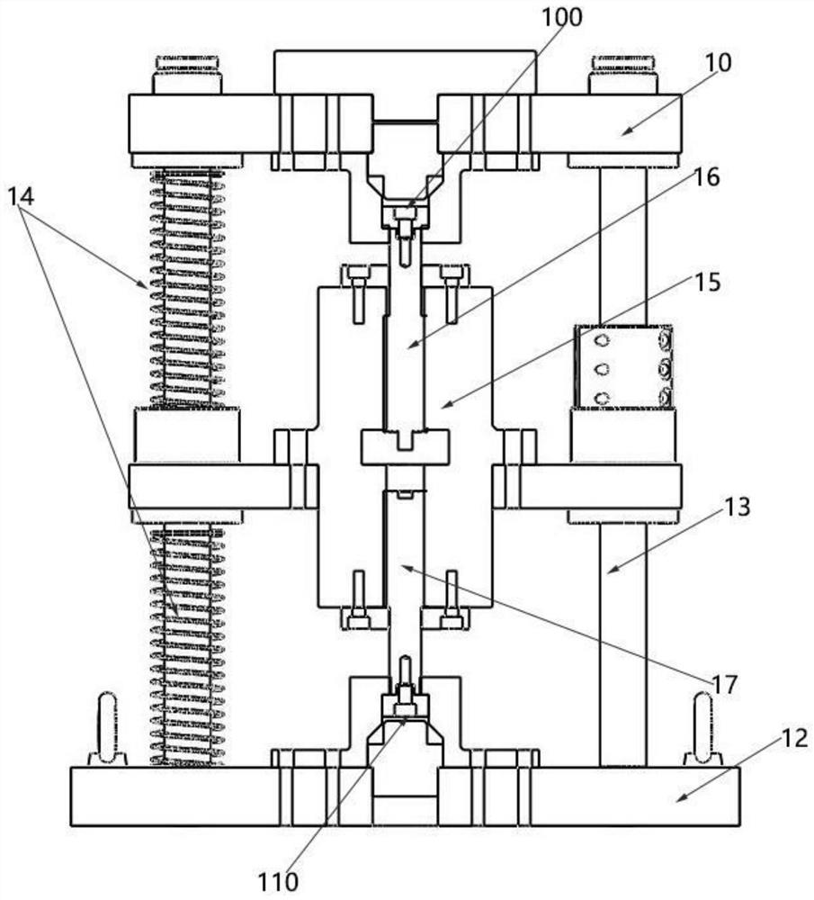
[0042] Such as Figures 1 to 5 As shown, a shaping formwork includes a formwork upper plate 10, a connecting plate 11 and a formwork lower plate 12, and the formwork upper plate 10, connecting plate 11 and formwork lower plate 12 pass through the guide column 13 sequentially from top to bottom Connection, the formwork lower plate 12 is fixedly connected with the guide column 13, the formwork upper plate 10 and the connecting plate 11 are all slidably connected with the guide column 13, and the formwork upper plate 10 and the connect...


PUM


Abstract

The invention belongs to the technical field of conventional sizing devices for powder metallurgy products, and particularly relates to a sizing die set and a finishing machine with the sizing die set. The sizing die set comprises a die set upper plate, a connecting plate and a die set lower plate, wherein the die set upper plate, the connecting plate and the die set lower plate are sequentially connected through guide columns from top to bottom, the die set lower plate is fixedly connected with the guide columns, the die set upper plate and the connecting plate are both in sliding connection with the guide columns, springs are arranged between the die set upper plate and the connecting plate and between the connecting plate and the die set lower plate, a sizing sleeve is fixed to the connecting plate, an upper sizing core rod is fixed to the die set upper plate and extends into the sizing sleeve through the upper part of the sizing sleeve, and a lower sizing core rod is fixed to the die set lower plate and extends into the sizing sleeve through the lower part of the sizing sleeve. The die set upper plate, the connecting plate and the die set lower plate are connected through the guide columns, so that the precision in the sizing and moving process can be guaranteed as long as the machining precision of the die set upper plate, the connecting plate, the die set lower plate and the guide columns is guaranteed, and finally the sizing precision of products is guaranteed.

Description

technical field [0001] The invention belongs to the technical field of conventional shaping devices for powder metallurgy products, and in particular relates to a shaping mold base and a finishing machine thereof. Background technique [0002] The traditional powder metallurgy shaping process generally uses a mechanical or hydraulic punching machine to install a shaping mold between the upper and lower panels. By adjusting the position of the shaping mold and applying a certain pressure to the product, the size, surface hardness and contour accuracy of the product are improved. However, the parallelism of the products currently produced should be within 0.02mm, and the flatness should be within 0.01mm. It is difficult to adjust the product tolerance to the median value. As a result, the quality of the product cannot fully meet the requirements, and the accuracy of most punching machines is above 2 wires. The existing technology cannot fully meet the technical requirements o...

Claims


Application Information

Patent Timeline
Patent Type & Authority Applications(China)
IPC IPC(8): B21D37/10B21D43/12B21D45/04
CPCB21D37/10B21D43/12B21D45/04
Inventor 王京
Owner SHANXI XINHUAN POWDER METALLURGY
Why Eureka
Try Eureka