
Aerated concrete isometric block equipment for eco-friendly construction

A technology of aerated concrete and construction, applied in metal processing, ceramic molding machines, manufacturing tools, etc., can solve the problems of difficult cutting and inconvenient movement, and achieve the effect of automatic blanking

Active Publication Date: 2022-03-11
江西经匠建设有限公司
View PDF20 Cites 0 Cited by
  • Summary
  • Abstract
  • Description
  • Claims
  • Application Information

AI Technical Summary

Problems solved by technology

[0004] In order to overcome the disadvantages of inconvenient movement and difficult cutting of the existing cutting equipment, the technical problem of the present invention is to provide an equidistant aerated concrete block equipment for environmentally friendly buildings that can be easily cut

Method used


Image

  • Aerated concrete isometric block equipment for eco-friendly construction
  • Aerated concrete isometric block equipment for eco-friendly construction
  • Aerated concrete isometric block equipment for eco-friendly construction

Examples


Embodiment 1

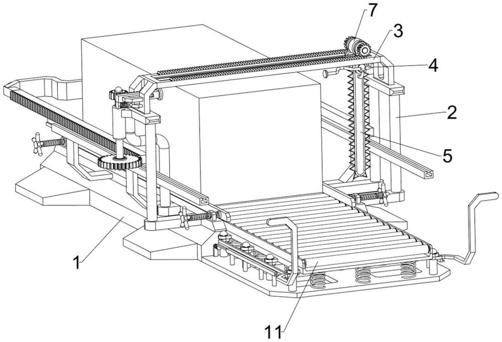
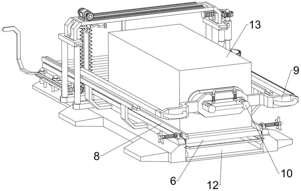
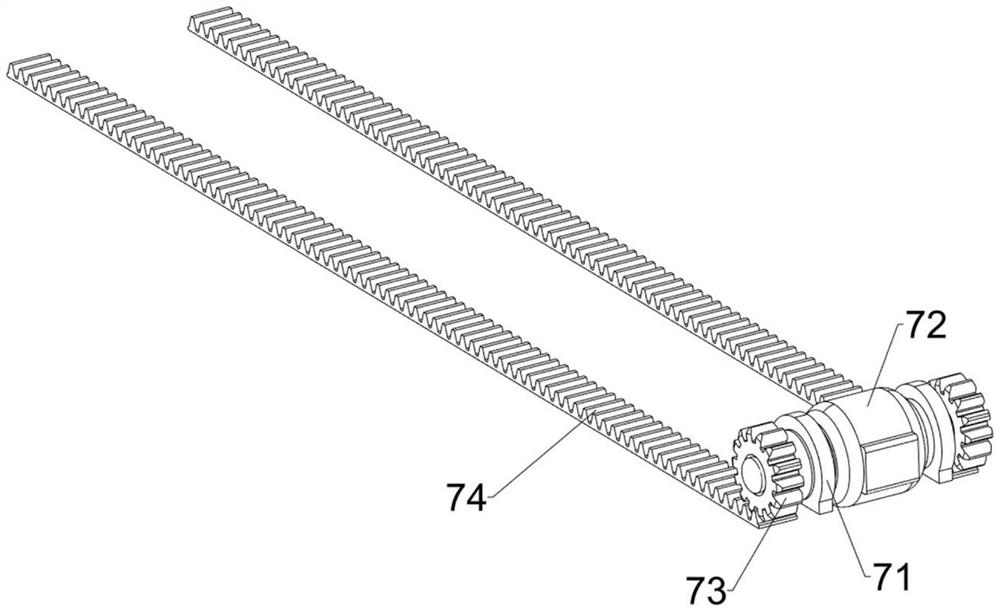
[0028] Aerated concrete isometric block equipment for eco-friendly construction such as Figure 1-4 As shown, it includes a bottom plate 1, a fixed frame 2, a first guide rail frame 3, a first mounting frame 4, an electric cutting saw 5, a rotating roller 6, a reciprocating mechanism 7 and a width adjustment mechanism 8, and the left and right sides of the front part of the bottom plate 1 are all A fixed frame 2 is connected, and a first guide rail frame 3 is connected between the tops of the fixed frame 2, and a first mounting frame 4 is slidably connected to the first rail frame 3, and an electric cutting saw 5 is arranged on the first mounting frame 4. 1 The upper part is uniformly rotatably connected with a roller 6, a reciprocating mechanism 7 is provided between the first rail frame 3 and the first installation frame 4, and a width adjustment mechanism 8 is provided on the rear side of the bottom plate 1.

[0029] The reciprocating mechanism 7 includes a connecting frame...

Embodiment 2

[0033] On the basis of Example 1, such as Figure 5-9As shown, a pusher mechanism 9 is also included, and the pusher mechanism 9 includes a trigger lever 91, a sliding frame 92, a positioning block 93, a first fixed seat 94, a first return spring 95, a second rack 96, a second gear 97. Transmission shaft 98, fixed ring sleeve 99, one-way clutch 910, third gear 911, third rack 912, push plate 913, guide frame 914, second guide rail frame 915 and handle ring 916, first mounting frame 4 The left side is provided with a trigger lever 91, and the left front side of the first guide rail frame 3 is provided with a positioning block 93, and the positioning block 93 is slidably connected with a sliding frame 92, and the rear side of the sliding frame 92 is provided with a second rack 96, and the first guide rail The lower part of the left front side of the frame 3 is provided with a first fixed seat 94, the first return spring 95 is connected between the left side of the first fixed se...


PUM


Abstract

The invention relates to equidistant block equipment, in particular to an aerated concrete equidistant block equipment used for environment-friendly buildings. The technical problem of the present invention is to provide an aerated concrete equidistant block equipment for environment-friendly buildings that can be easily cut. The technical embodiment of the present invention is: an aerated concrete equidistant block equipment for environmentally friendly buildings, including a base plate, a fixing frame, a first guide rail frame, a first mounting frame, an electric cutting saw and a rotary kun, the front of the base plate Both sides of the head are connected with a fixed frame, the top of the fixed frame is connected with a first rail frame, the first rail frame is slidably connected with a first mounting frame, the first mounting frame is equipped with an electric cutting saw, and the upper part of the base plate rotates evenly The connection has a turn Kun. Through the cooperation between the pushing mechanism, the reciprocating mechanism and the width adjusting mechanism, the concrete can be conveyed at intervals and the concrete can be cut equidistantly.

Description

technical field [0001] The invention relates to equidistant block equipment, in particular to an aerated concrete equidistant block equipment used for environment-friendly buildings. Background technique [0002] The interior of the concrete is mainly composed of some building materials such as lime sand and stone mixed with water, which play a fixed role. However, for different places, the size of the concrete used is different, but the area that is too small is used in the manufacture of concrete blocks. It is relatively inconvenient, so multiple concrete blocks are required to be produced intensively, and then cut. Due to the material inside the concrete, if there is uneven mixing, there will be a lot of dust when cutting, and the traditional In mobile cutting, manual hand-held cutting tools are relatively difficult. [0003] Therefore, in order to solve these problems and make the cutting more convenient, it is necessary to design an aerated concrete equidistant block e...

Claims


Application Information

Patent Timeline
Patent Type & Authority Patents(China)
IPC IPC(8): B26D1/06B28B11/14
CPCB28B11/14
Inventor 王玉龙
Owner 江西经匠建设有限公司
Learn More