
Frame structure unloading and column pulling structure and construction method thereof

A technology of frame structure and construction method, applied in the direction of building structure, building maintenance, construction, etc., to achieve the effect of facilitating the removal of the jack and ensuring the load strength

Pending Publication Date: 2021-05-07
武汉鼎盛力华工程技术有限公司
View PDF1 Cites 2 Cited by
  • Summary
  • Abstract
  • Description
  • Claims
  • Application Information

AI Technical Summary

Problems solved by technology

[0005] In order to improve the convenient operation of pulling columns, the application provides a frame structure unloading column pulling structure and its construction method

Method used


Image

  • Frame structure unloading and column pulling structure and construction method thereof
  • Frame structure unloading and column pulling structure and construction method thereof
  • Frame structure unloading and column pulling structure and construction method thereof

Examples


Embodiment 1

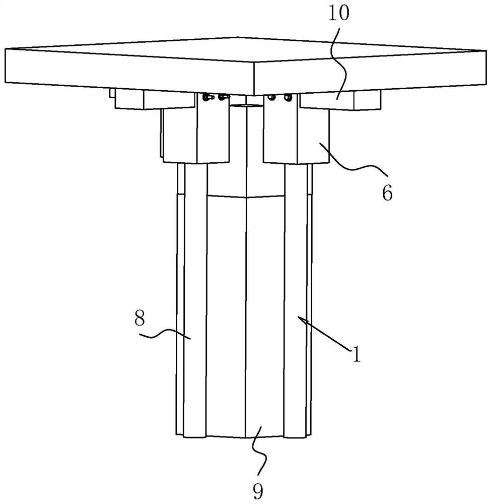
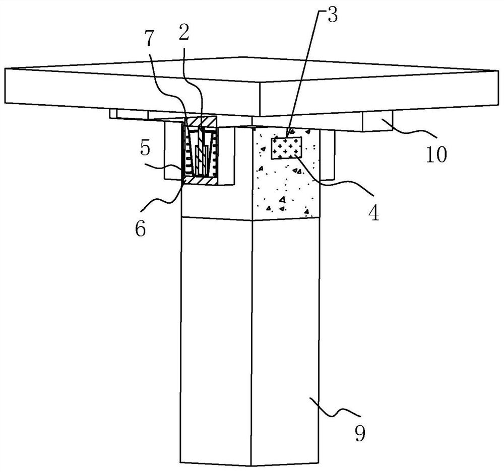
[0047] The embodiment of the present application discloses a frame structure unloading column pulling structure. refer to figure 1 , the frame structure unloading column structure includes three support bases 1 and the jack 2 installed on the support base 1, the support base 1 is composed of a steel support 8, the steel support 8 is placed on the ground, and the jack 2 is placed on the top of the steel support 8 Above, the output end of the jack 2 abuts against the original load-bearing beam 10, the position where the jack 2 abuts against the original load-bearing beam 10 is close to the original load-bearing column 9, and the three original load-bearing beams 10 around the original load-bearing column 9 are supported by the jack 2 The load-bearing effect of the original load-bearing column 9 on the original load-bearing beam 10 is realized under the action.

[0048] refer to figure 1 and figure 2, the original load-bearing column 9 on the side where the jack 2 is not set ...

Embodiment 2

[0054] The embodiment of the present application discloses a construction method of a frame structure unloading column pulling structure. refer to image 3 , the construction method of frame structure unloading column structure includes the following steps,

[0055] S1. Jack 2 is unloaded, and a steel support platform 8 is built to form a support seat 1, which supports three points of two original load-bearing beams 10 around the original load-bearing column 9. -2t, the position where the jack 2 abuts against the original load-bearing beam 10 is close to the original load-bearing column 9, further ensuring the safe unloading work of the original load-bearing column 9 to the original load-bearing beam 10 after drilling;

[0056] S2, drilling, the original load-bearing column 9 is located at the lower part of the beam to carry out core drilling to form a through hole 3, the through hole 3 is set through, and the length direction of the through hole 3 is along the length directi...


PUM


Abstract

The invention relates to a frame structure unloading and column pulling structure and a construction method thereof, and relates to the field of building construction.The frame structure unloading and column pulling structure comprises a plurality of supporting bases and jacks installed on the supporting bases, and the output ends of the jacks abut against bearing beams; and bearing columns are provided with orthogonal through holes, the length direction of the through holes is the same as the length direction of the corresponding original bearing beams, the bearing columns are provided with concrete layers in the through holes in a pouring mode, the bearing beams are connected with a reinforcing mesh, and the reinforcing mesh is internally provided with a fixing assembly facilitating dismounting of the jacks. The frame structure unloading and column pulling structure has the effect that the bearing beams can be conveniently unloaded through the bearing columns, the safety and convenience of column pulling operation are improved, the construction period of column pulling construction is greatly shortened, traceless cutting is adopted in the construction process, and the environment-friendly performance is achieved.

Description

technical field [0001] The present application relates to the field of building construction, in particular to a frame structure unloading column structure and a construction method thereof. Background technique [0002] Pulling out joist beams is a comprehensive technology to cut off part (or all) of the columns without demolishing the upper structure of the structure. It is mainly suitable for increasing the use space or changing the plane layout due to functional changes. Joist pulling column is a general term for supporting roof truss pulling column, joist wall removal and joist pulling column. It is a comprehensive technology to remove the middle column or wall without demolishing or removing the superstructure. At present, in order to adapt to further development in the future, many units often hope to remove the columns or walls of certain buildings to expand their use space, and during the renovation process, the normal use function of the structure can not be affect...

Claims


Application Information

Patent Timeline
IPC IPC(8): E04G23/02E04G23/08
CPCE04G23/02E04G23/08
Inventor 缪力刘俊华叶施虎付万军
Owner 武汉鼎盛力华工程技术有限公司
Learn More