Short-range correction calibration method suitable for laser scanner

A technology of laser scanners and calibration methods, applied in the direction of using optical devices, instruments, measuring instruments, etc.

Active Publication Date: 2021-05-07
SHANGHAI JING HAI ENG TECH CO LTD
View PDF4 Cites 4 Cited by
  • Summary
  • Abstract
  • Description
  • Claims
  • Application Information

AI Technical Summary

Problems solved by technology

[0004] The purpose of the present invention is to solve the short-range correction and calibration problem of the laser scanner in the tunnel mobile scanning system, and proposes a short-range correction and calibration method suitable for laser scanners. This method simulates the tunnel short-range ranging environment , arrange multiple pairs of target balls on both sides of the scanner, use the laser scanner to collect the target ball point cloud in the two-dimensional helical scanning mode, and obtain multiple pairs of target ball centers through circle fitting and center conversion operations. Coordinates, and then indirectly obtain the center distance of multiple pairs of target balls, compare this distance with the center distance measured by the total station, and finally get the short-range correction calibration value of the laser scanner

Method used


Image

  • Short-range correction calibration method suitable for laser scanner
  • Short-range correction calibration method suitable for laser scanner
  • Short-range correction calibration method suitable for laser scanner

Examples


Embodiment Construction

[0044] Attached below Figure 1-3 , give preferred embodiments of the present invention, and further illustrate the present invention.

[0045] The present invention comprises steps as follows.

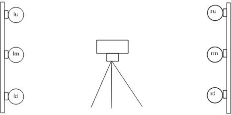
[0046] S1: Arrange multiple pairs of target balls on both sides of the scanning line of the laser scanner.

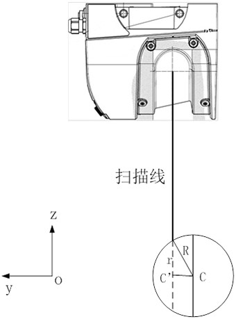
[0047] S2: Use the scanner to scan separately to obtain the coordinates of the center of the target ball.

[0048] S3: Use the total station to measure and obtain the coordinates of the center of the target ball respectively.

[0049] S4: Screen out the target balls that can be used for calibration.

[0050] S5: Calculating the short-range correction value.

[0051] S1: According to figure 1 As shown, multiple pairs of target balls are arranged on both sides of the scanning line of the laser scanner. In this embodiment, three pairs of target balls are arranged, namely lu-ru, lm-rm, and ld-rd. The distance between the target balls and the scanner is about 3m. , similar to ...


PUM


Abstract

The invention relates to a short-range correction calibration method suitable for a laser scanner. The method comprises the following steps: S1, respectively arranging a plurality of pairs of target balls on two sides of a scanning line of the laser scanner; S2, scanning by using a scanner to obtain the center coordinates of the target ball; S3, using a total station for measuring and obtaining the center coordinates of the target ball; S4, screening out target balls which can be used for calibration; and S5, calculating a short-range correction value. The invention has the following advantages: 1) the problem of short-range calibration of the scanner in subway tunnel mobile scanning is solved; 2) a metro tunnel measurement distance and a measurement mode are simulated to carry out target ball arrangement, wherein a calibration result is more in line with a tunnel measurement use environment; 3) the center of the target ball is fitted by scanning points of the scanning target ball, the algorithm precision is high, the robustness is strong, and 4) the operation is simple and convenient, and the method is suitable for practical engineering application.

Description

technical field [0001] The invention relates to the technical field of tunnel monitoring, and specifically designs a short-range correction and calibration method suitable for laser scanners. Background technique [0002] In recent years, with the rapid development of my country's urban rail transit industry, the mileage of subway tunnels has continued to increase, and the requirements for safety monitoring of subway tunnels have also been continuously improved. In this context, the use of laser scanners for subway tunnel detection has gradually become an important technical means in the safety inspection of subway tunnels, especially the mobile subway tunnel detection system equipped with laser scanners has been widely used. [0003] In the mobile subway tunnel detection system, the ranging accuracy of the laser scanner directly affects the tunnel detection accuracy of the system as a whole. In practical engineering applications, it is found that the laser scanner is used i...

Claims


Application Information

Patent Timeline
Patent Type & Authority Applications(China)
IPC IPC(8): G01C15/00G01B11/00G01C25/00
CPCG01C15/00G01B11/002G01C25/00
Inventor 王子轩贺祎侃
Owner SHANGHAI JING HAI ENG TECH CO LTD
Why Eureka
Try Eureka