Optical fiber connector and optical fiber connection structure

A fiber optic connector and connection cavity technology, applied in light guides, optics, instruments, etc., can solve the problems affecting the coupling accuracy of connectors and adapters, mechanical wear, etc., to ensure the transmission effect of optical fiber communication, prolong the service life, realize connection and Disconnected effect

Pending Publication Date: 2021-05-07
WUHAN UF OPTOELECTRIC TECH CO LTD
View PDF0 Cites 2 Cited by
  • Summary
  • Abstract
  • Description
  • Claims
  • Application Information

AI Technical Summary

Problems solved by technology

[0005] In order to solve the problem that the existing optical fiber connection structure is prone to mechanical wear during the unlocking process, thereby affecting the coupling accuracy of the connector and the adapter, the purpose of the present invention is to provide a new type of optical fiber connector and optical fiber connection structure that can be unlocked based on a rotating structure. It can avoid mechanical wear during the unlocking process, thereby ensuring the service life of the connector and the coupling accuracy of the connector and the adapter during connection and use

Method used


Image

  • Optical fiber connector and optical fiber connection structure
  • Optical fiber connector and optical fiber connection structure
  • Optical fiber connector and optical fiber connection structure

Examples


Embodiment 1

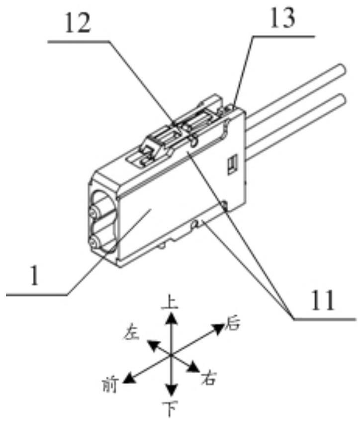
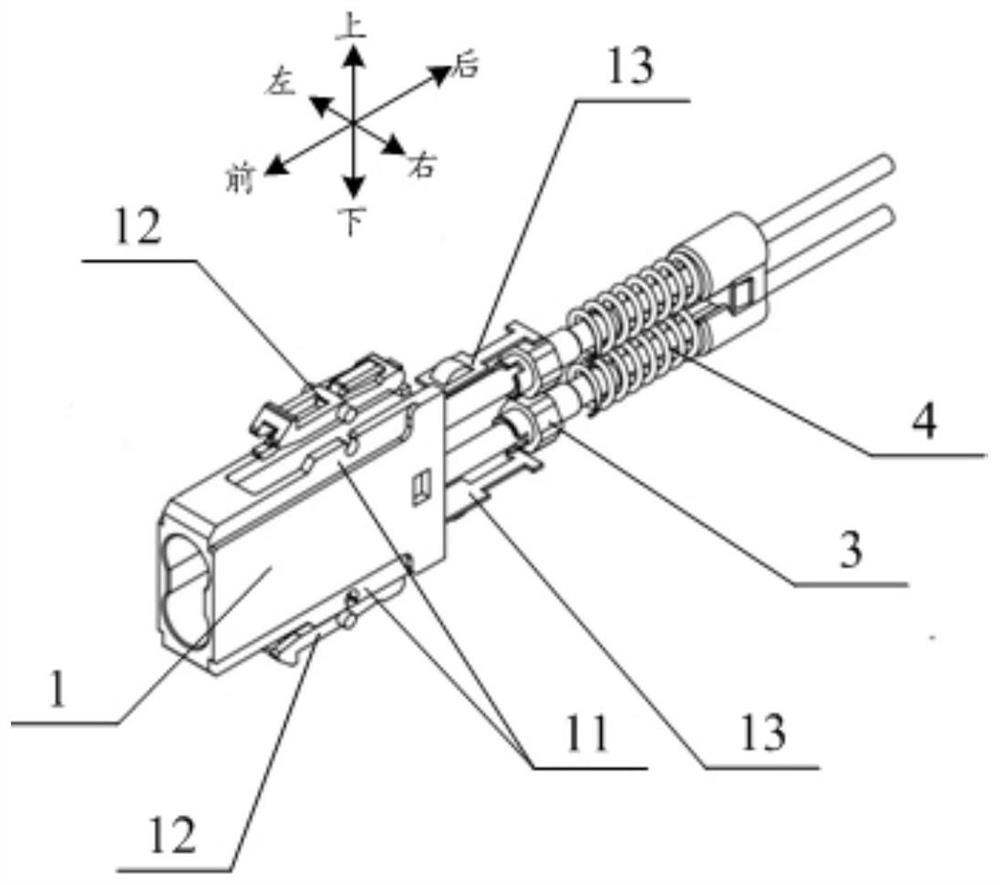
[0070] Such as Figure 2-15 As shown, the first optical fiber connector provided in this embodiment includes a connection housing 1 for plugging and mating with the adapter end connection cavity 2, and also includes an extension support body 11, a locking clip 12, and an elastic member. 124 and a latch height control member 13, wherein, the extension support body 11 is fixed on the outer surface of the connection housing 1, and a shaft hole 111 is opened on the outwardly extending end of the extension support body 11; The lock clip 12 includes a rotating shaft 121, a latch 122, and a stop portion 123, wherein the latch 122, the rotating shaft 121, and the stop portion 123 are sequentially arranged at intervals from front to back and sequentially fixed connection, the front-to-back direction is opposite to the inserting direction of the plug fit; the rotating shaft 121 is rotationally fitted in the shaft hole 111, and the latch 122 can be positioned in the shaft hole 111 Rotat...

Embodiment 2

[0089] Such as Figures 16-18 As shown, this embodiment provides a second optical fiber connector on the basis of the technical solution of the first embodiment, which differs from the technical solution of the first embodiment in that: the first limiting boss 132 The extraction surface 14 adopts another limited fit structure, and the second limit boss 133 and the insertion surface 15 adopt another limited fit structure; When the extension support body 11, the lock clip 12 and the latch height control member 13 are symmetrically arranged on the outer surfaces of opposite sides, the two symmetrically arranged latch heights are respectively connected through the hollow body 16. the tail of the control member 13, and make the two symmetrically arranged first limiting bosses 132 align with each other, and make the symmetrically arranged two said second limiting bosses 133 align or coincide with each other, so that the push-pull The hollow body 16 moves the two latch height contro...

Embodiment 3

[0092] Such as Figure 19-20 As shown, this embodiment provides a third optical fiber connector on the basis of the technical solution of the second embodiment, which is different from the technical solution of the second embodiment in that: one end of the cantilever structure is fixedly connected The bottom surface of the front part of the first space 112 , the other end of the cantilever structure is in contact with the middle bottom surface of the lock clip 12 , that is, the elastic member 124 is separated from the lock clip 12 . Therefore, through the above-mentioned structural design, the elastic member 124 can also have the ability to recover from deformation when it is in the squeezed state, so as to achieve the purpose of automatic reset in this embodiment.

[0093] The technical effect of this embodiment can be directly derived by referring to the technical effect of the second embodiment, and will not be repeated here.


PUM


Abstract

The invention relates to the technical field of optical fiber communication, discloses an optical fiber connector and an optical fiber connection structure, and provides a design scheme of a novel optical fiber connector capable of being unlocked based on a rotating structure. A lock toggle clip installed outside a connecting shell is designed to be a forepoling arm which can achieve locking and buckling with an adapter side locking structure through the elastic deformation recovery effect and can achieve friction-free unlocking between a latch and the adapter side locking structure through the seesaw principle. On one hand, it can be ensured that the latch on the connector end and the locking structure on the adapter end are locked tightly, and on the other hand, the latch and the locking structure are gradually separated in a back-to-back mode in the unlocking process, so that friction force can be gradually reduced, mechanical abrasion to a locking component in the unlocking process can be avoided, the service life of the connector is prolonged, and the coupling precision of the connector and the adapter and the optical fiber communication transmission effect during subsequent connection and use are guaranteed.

Description

technical field [0001] The invention belongs to the technical field of optical fiber communication, and relates to miniaturized and encapsulated connectors and adapter products for optical fiber physical connection, in particular to an optical fiber connector and an optical fiber connection structure. Background technique [0002] The connection between optical fiber and optical fiber, as well as the connection between optical fiber and equipment, is basically realized through connectors. With the explosive growth of information Internet and cloud services, the requirements for optical fiber connection density are also constantly increasing. That is to realize more optical fiber connections in a unit volume. [0003] At present, when unlocking an optical fiber connector and an adapter in a traditional optical fiber connection structure, the connector shrapnel must be further forcibly squeezed and deformed before it can be separated from the corresponding matching structure o...

Claims


Application Information

Patent Timeline
Patent Type & Authority Applications(China)
IPC IPC(8): G02B6/38
CPCG02B6/3825G02B6/387
Inventor 张迪
Owner WUHAN UF OPTOELECTRIC TECH CO LTD
Why Eureka
Try Eureka