Machine room inspection method and device

A technology for computer rooms and inspection points, applied in inspection time patrols, computer parts, instruments, etc., can solve the problems of false detection, false detection or missed detection, easy to be affected by external environment, increased detection cost, etc., and achieve data reduction. , The effect of improving generalization ability and reducing workload

Active Publication Date: 2021-05-07
QUANZHOU POWER SUPPLY COMPANY OF STATE GRID FUJIAN ELECTRIC POWER +2
View PDF5 Cites 8 Cited by
  • Summary
  • Abstract
  • Description
  • Claims
  • Application Information

AI Technical Summary

Problems solved by technology

In the existing technology, the network management system cannot monitor the state of the air switch, and can only be detected through manual detection or fixed camera monitoring. Both methods have defects: manual detection, due to the subjective factors of the personnel themselves, is easy to cause false detection , False detection or missed detection; the detection method of fixed camera monitoring has a limited detection range, and when the number of devices to be detected increases, the detection cost will also increase, and most of the detection methods of fixed camera monitoring use template matching algorithms for air switching State detection, this method is vulnerable to the external environment, and its robustness is poor

Method used


Image

  • Machine room inspection method and device
  • Machine room inspection method and device
  • Machine room inspection method and device

Examples


Embodiment Construction

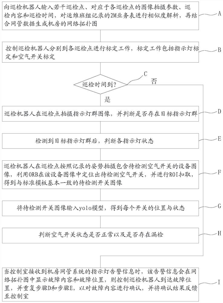
[0037] Such as figure 1 As shown, the computer room inspection method includes the following steps:

[0038] A. Use the mapping function of the inspection robot to build a two-dimensional planar map in the computer room, and set a number of inspection points on the map to realize the input of inspection points to the inspection robot and input corresponding to each inspection point to the inspection robot. The image shooting parameters, inspection content and inspection time of the inspection point, so that the robot regularly inspects the designated inspection point according to the inspection time. The inspection content includes switch state detection and indicator light state detection, and the image shooting parameters include Camera rotation and pitch angle and camera focal length, after completing the above preparations, place the inspection robot at the charging position; among them, the specific method of constructing a two-dimensional planar map is the existing techn...


PUM


Abstract

The invention provides a machine room inspection method, which comprises the following steps of: A, inputting a plurality of inspection points, image shooting parameters, inspection contents and the inspection time into an inspection robot, and generating a network topological graph; b, carrying out calibration work; c, performing routing inspection when the routing inspection time is up, otherwise, entering the step I; d, shooting an indicator lamp group image at the inspection point; e, detecting the state of an indicator lamp; f, shooting an equipment image containing the to-be-detected air switch, and positioning the to-be-detected air switch; g, inputting the to-be-detected switch image into the yolo model to obtain the position and the state of each switch; h, judging whether the air switch state is abnormal or not and whether leak detection exists or not; and I, receiving alarm information of the network management system, controlling the inspection robot to arrive at the fault position, and repeating the step D and the step E. The invention further provides a machine room inspection device. According to the invention, an accurate network topological graph can be generated, the detection with strong anti-interference performance, low false detection rate and high accuracy is achieved, and the inspection of the machine room is more comprehensive.

Description

technical field [0001] The invention relates to a machine room inspection method and device. Background technique [0002] In the operation and maintenance of the power communication computer room, the equipment in the computer room is mainly maintained by using the alarm of the network management system of the computer room and the manual inspection by the administrator, or the status of the equipment is checked by the robot through the inspection work order by identifying the indicator light Judgment and review by administrators. When the status of the indicator light of the equipment fails, after the control room determines the location of the fault through the network topology map, it can go to the fault location manually or by robot, review the fault, and proceed to the next step of processing. During the generation of the network topology diagram, a 2M business table needs to be imported. This business table is recorded by the operation and maintenance team and may be...

Claims


Application Information

Patent Timeline
Patent Type & Authority Applications(China)
IPC IPC(8): G06K9/00G06K9/32G06K9/46G06K9/62G06N3/04G07C1/20
CPCG06N3/049G07C1/20G06V20/10G06V10/25G06V10/462G06N3/044G06F18/214
Inventor 谢勇添林明福颜泗海郑军荣吴冠雄林保霖孙丽君
Owner QUANZHOU POWER SUPPLY COMPANY OF STATE GRID FUJIAN ELECTRIC POWER
Why Eureka
Try Eureka